3.1.2
Display unit LEDs and push-buttons
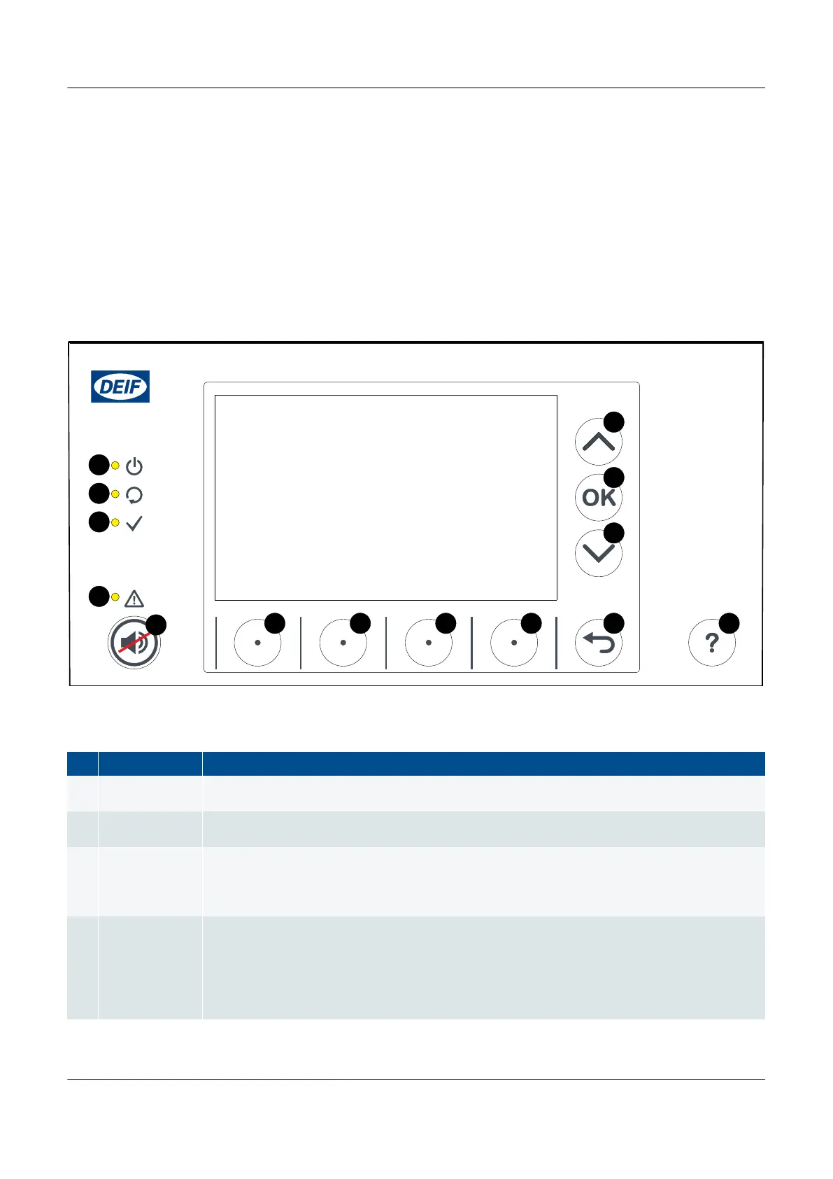
The top part of the front of the display unit is the same for all controller types. It includes LEDs that show the controller status
and a push-button to silence the alarm horn. The other push-buttons allow the operator to see controller information on the
display unit screen. The actual information available to the operator depends upon the permission access for the operator's
log on profile.* Using the push-buttons and the screen, the operator can see Live Data, or see, acknowledge and unlatch
alarms. If the operator logs in with the right permission level, he can also change the controller configuration.
* Some features or functions of the display unit may only be accessible if the user profile logged on has the necessary
permission access.
Figure 3.2
Display unit LEDs and push-buttons
Table 3.1 Display unit LED functions
No. Name Function
1
Display unit
power OK
Green: The display unit power is OK.
OFF: The display unit power is not OK.
2 Self-check OK
Green: The controller self-check is OK.
OFF: The controller self-check is not OK, or there is no connection to the controller
3
Ready for
operation
Green: The controller is not under switchboard control, and there is no alarm action (for example,
shutdown, trip or block) that prevents the controlled equipment from supplying power.
OFF: The controller is under switchboard control, or there is an alarm action that prevents the
controlled equipment from supplying power.
4 Alarm
Red (constant): Alarm(s) active, and all alarms acknowledged
Red (flashing): Unacknowledged alarm(s)
Yellow: Unlatched alarms can be reset (when no other alarms require action)
Yellow (flashing): Unacknowledged latched alarms.
Green (flashing): Only unacknowledged alarm(s) where the alarm condition has cleared
Green (constant): No alarms
PPM 300 Operator's manual 4189340910 UK
www.deif.com Page 25 of 157