Table 3.4 GENSET controller push-button functions
No. Name Function
1 Genset start
SEMI mode: The controller starts the genset start sequence.
AUTO mode or Switchboard control: The controller ignores the input from this push-button.
2 Genset stop
SEMI mode: The controller starts the genset stop sequence.
AUTO mode or Switchboard control: The controller ignores the input from this push-button.
3 Close breaker
SEMI mode: The controller starts the breaker close sequence.
AUTO mode or Switchboard control: The controller ignores the input from this push-button.
4 Open breaker
SEMI mode: The controller starts the breaker open sequence (if the PMS allows this).
AUTO mode or Switchboard control: The controller ignores the input from this push-button.
5 AUTO mode
SEMI mode: The controller changes to AUTO mode.
AUTO mode or Switchboard control: The controller ignores the input from this push-button.
6 SEMI mode
AUTO mode: The controller changes to SEMI mode.
SEMI mode or Switchboard control: The controller ignores the input from this push-button.
7 1st priority
The controller gives the genset the first priority in the genset start order in the power management
system.
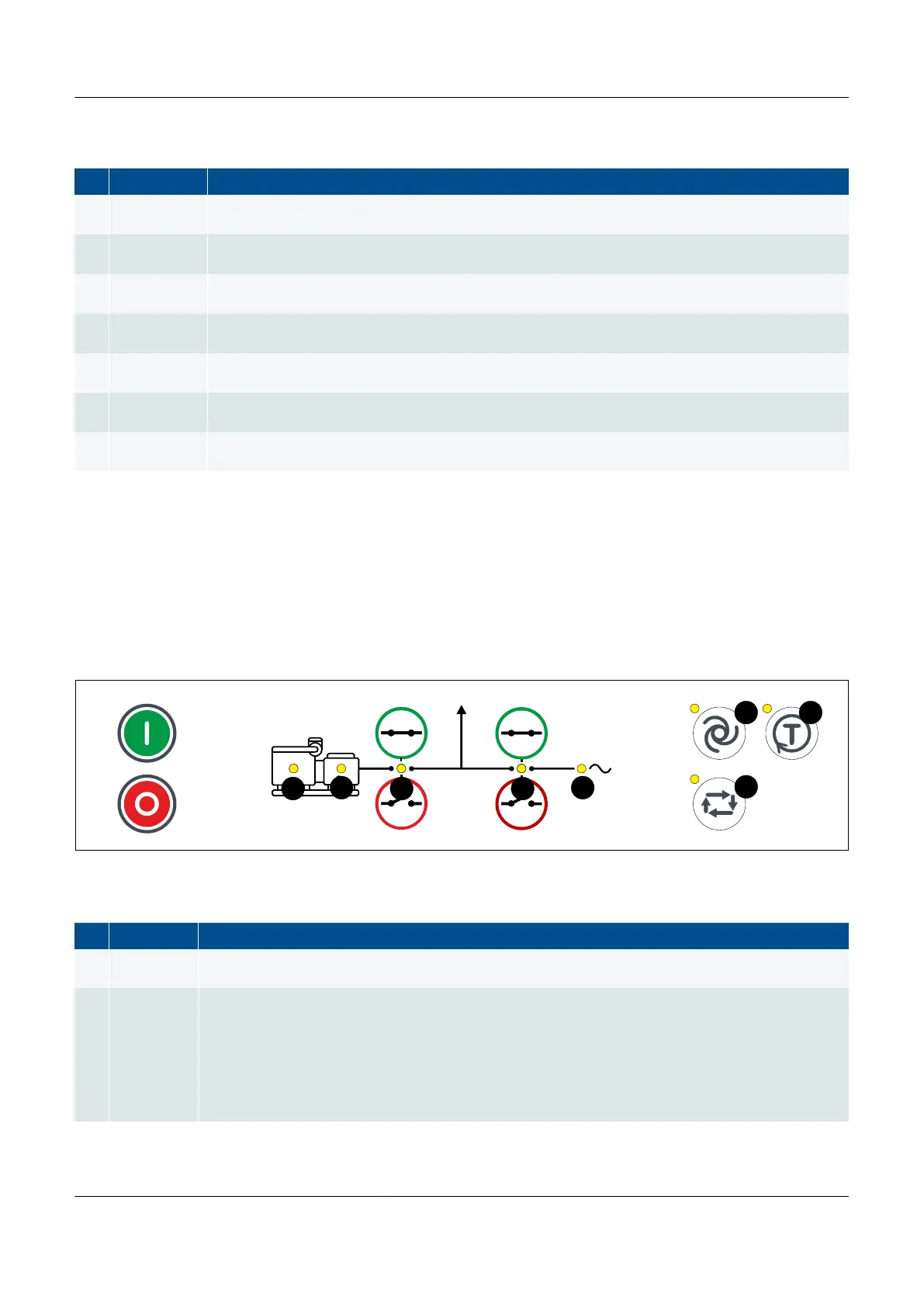
3.1.4 EMERGENCY genset controller LEDs and push-buttons
The bottom strip of the front of the display unit is customised for the EMERGENCY genset controller. It includes LEDs that
show the equipment and controller status, as well as push-buttons for operator actions.
EMERGENCY genset controller LEDs
Figure 3.5
EMERGENCY genset controller display unit LEDs
Table 3.5 EMERGENCY genset controller LED functions
No. Name Function
1 Engine
Green: There is running feedback.
OFF: The engine is not running, or there is no running feedback.
2 Generator
Green: The generator voltage and frequency are OK, and the controller can synchronise and close the
breaker.
Green (flashing): The generator voltage and frequency are OK, but the V&Hz OK timer is still running.
The controller cannot close the breaker.
Yellow: The generator voltage and frequency are measurable, but not OK. The controller cannot close
the breaker.
OFF: The generator voltage is too low to measure.
PPM 300 Operator's manual 4189340910 UK