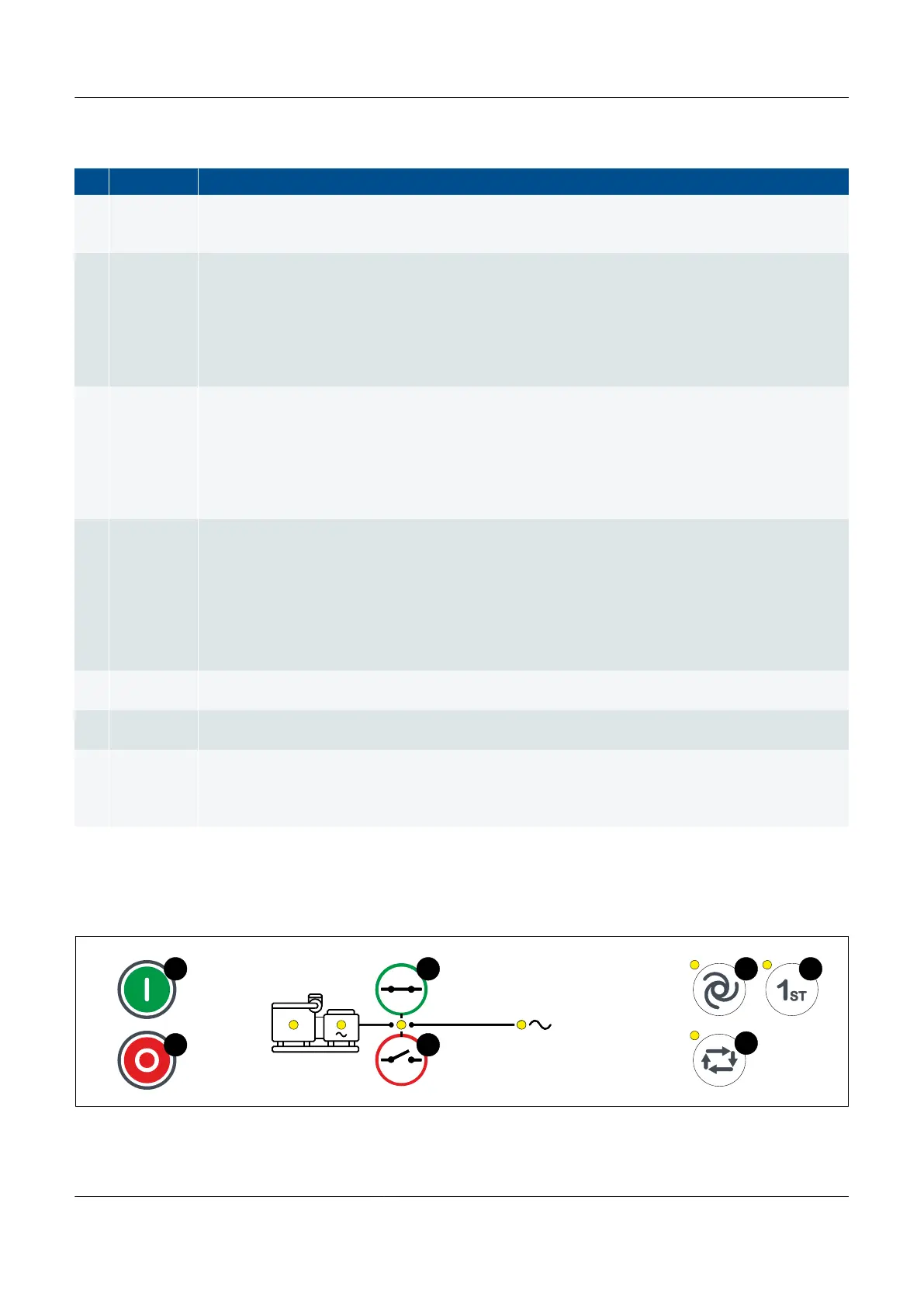
Table 3.3 GENSET controller LED functions
No. Name Function
1 Engine
Green: There is running feedback. Oil pressure, RPM, frequency above configured limit.
Green (flashing): Engine is becoming ready.
OFF: The engine is not running, or there is no running feedback.
2 Generator
Green: The generator voltage and frequency are OK, and the controller can synchronise and close the
breaker.
Green (flashing): The generator voltage and frequency are OK, but the V&Hz OK timer is still running.
The controller cannot close the breaker.
Yellow: The generator voltage and frequency are measurable, but not OK. The controller cannot close
the breaker.
OFF: The generator voltage is too low to measure.
3 Breaker
Green: The breaker is closed.
Yellow: The breaker spring is charging (only applies to a compact breaker).
Yellow (flashing): The controller is synchronising or de-loading the breaker.
Red: The controller tripped the breaker, and the trip alarm is unacknowledged and/or the alarm
condition is still present.
Red (flashing): Any generator breaker trip alarm is active.
OFF: The breaker is open.
4 Busbar
Green: The busbar voltage and frequency are OK, and the controller can synchronise and close the
breaker.
Green (flashing): The busbar voltage and frequency are OK, but the V&Hz OK timer is still running.
The controller cannot close the breaker.
Yellow: The busbar voltage and frequency are measurable, but not OK.
Red: The busbar voltage is too low to measure (for example, during a blackout). The controller can
close the breaker.
Red (flashing): The blackout detection timer is running and the controller is checking the busbar.
5 AUTO mode
Green: The controller is in AUTO mode.
OFF: The controller is not in AUTO mode.
6 SEMI mode
Green: The controller is in SEMI mode.
OFF: The controller is not in SEMI mode.
7 1st priority
Green: The genset has the first priority in the genset start order in the power management system.
Yellow: The genset is next in the genset start order in the power management system.
OFF: Another genset has first priority, or the power management system automatically calculates the
genset priority, or the controller is under SWBD control.
GENSET controller push-buttons
Figure 3.4
GENSET controller display unit push-buttons
PPM 300 Operator's manual 4189340910 UK
www.deif.com Page 27 of 157