No. Name Function
3 Breaker
Green: The breaker is closed.
Yellow: The breaker spring is charging (only applies to a compact breaker).
Yellow (flashing): The controller is synchronising or de-loading the breaker.
Red: The controller tripped the breaker, and the trip alarm is unacknowledged and/or the alarm
condition is still present.
Red (flashing): Any generator breaker trip alarm is active.
OFF: The breaker is open.
4 Tie breaker
Green: The tie breaker is closed.
Yellow: The tie breaker spring is charging (only applies to a compact breaker).
Yellow (flashing): The controller is synchronising or de-loading the tie breaker.
Red: The controller tripped the tie breaker, and the trip alarm is unacknowledged and/or the alarm
condition is still present.
Red (flashing): Any tie breaker trip alarm is active.
OFF: The tie breaker is open.
5 Busbar
Green: The busbar voltage and frequency are OK, and the controller can synchronise and connect to
the busbar.
Green (flashing): The busbar voltage and frequency are OK, but the V&Hz OK timer is still running.
The controller cannot connect to the busbar.
Yellow: The busbar voltage and frequency are measurable, but not OK.
Red: The busbar voltage is too low to measure (for example, during a blackout). The controller can
connect to the busbar.
Red (flashing): The blackout detection timer is running and the controller is checking the busbar.
6 AUTO mode
Green: The controller is in AUTO mode.
OFF: The controller is not in AUTO mode.
7 SEMI mode
Green: The controller is in SEMI mode.
OFF: The controller is not in SEMI mode.
8 Test
Green: The controller is running a test sequence (starts the emergency generator, and synchronises
and closes the generator breaker). The actual test depends on the test configuration in the controller.
OFF: The controller is not running a test.
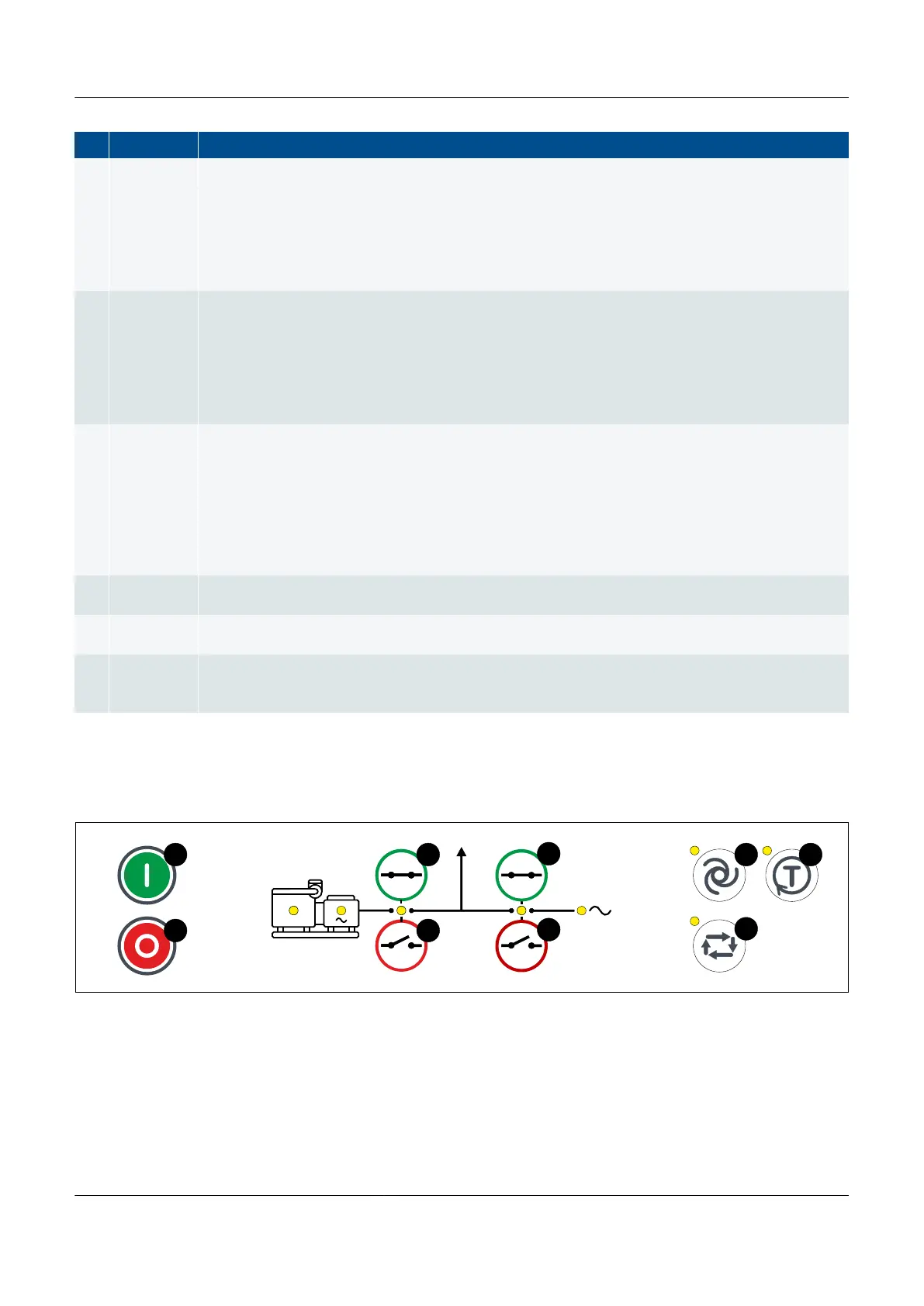
EMERGENCY genset controller push-buttons
Figure 3.6
EMERGENCY genset controller display unit push-buttons
PPM 300 Operator's manual 4189340910 UK
www.deif.com Page 29 of 157