(28) Screw on outer adjuster and tighten adjuster
down finger tight (Fig. 211).
(29) Insert special tool 6548 (Fig. 212). This tool
will be used to check turning torque of the differen-
tial assembly.
CAUTION: Differential bearings must be seated
before taking turning torque readings. This is done
by rotating the differential three or four turns in
both directions.
CAUTION: Turning torque of 19 to 23 in. lbs. can
only be obtained when using new bearings. Do not
attempt to obtain this turning torque with used
bearings.
(30) Tighten outer adjuster with tool 6503 until 19
to 23 in. lbs. of turning torque is obtained on tool
6548. Record how many foot pounds were
required on the outer adjuster to obtain the
correct turning torque (Fig. 213). Record the foot
pound reading. The reading that you are recording
will be used in Step 54 of this procedure.
(31) Remove the differential cover, differential car-
rier assembly and inner adjuster.
(32) At this point the amount of torque required
on the outer differential adjuster has been deter-
mined. The transfer shaft can now be installed into
the transaxle case. Perform the following steps to
install transfer shaft into transaxle case.
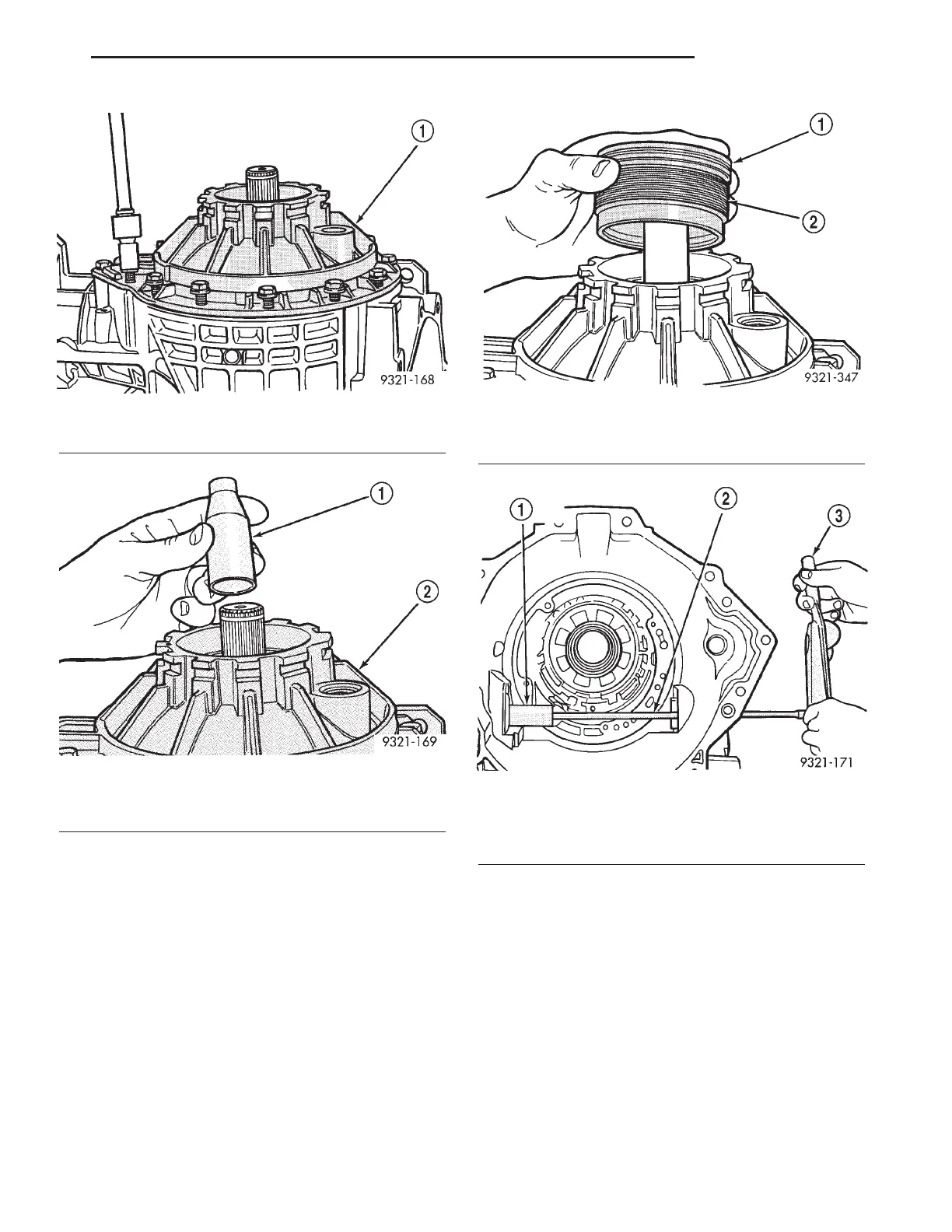
Fig. 209 Differential Cover Installation
1 - SIDE COVER
Fig. 210 Seal Protector
1 - SEAL PROTECTOR (6591)
2 - SIDE COVER
Fig. 211 Outer Adjuster Installation
1 - O-RING
2 - OUTER ADJUSTER
Fig. 212 Special Tool 6548
1 - SPECIAL TOOL 6548
2-
1
⁄
4
9 EXTENSION
3 - TORQUE WRENCH
LH TRANSAXLE 21 - 89
FINAL DRIVE (Continued)