Above Ground Model 200iX/250iX Motorcycle Dynamometer Installation Guide
2-36
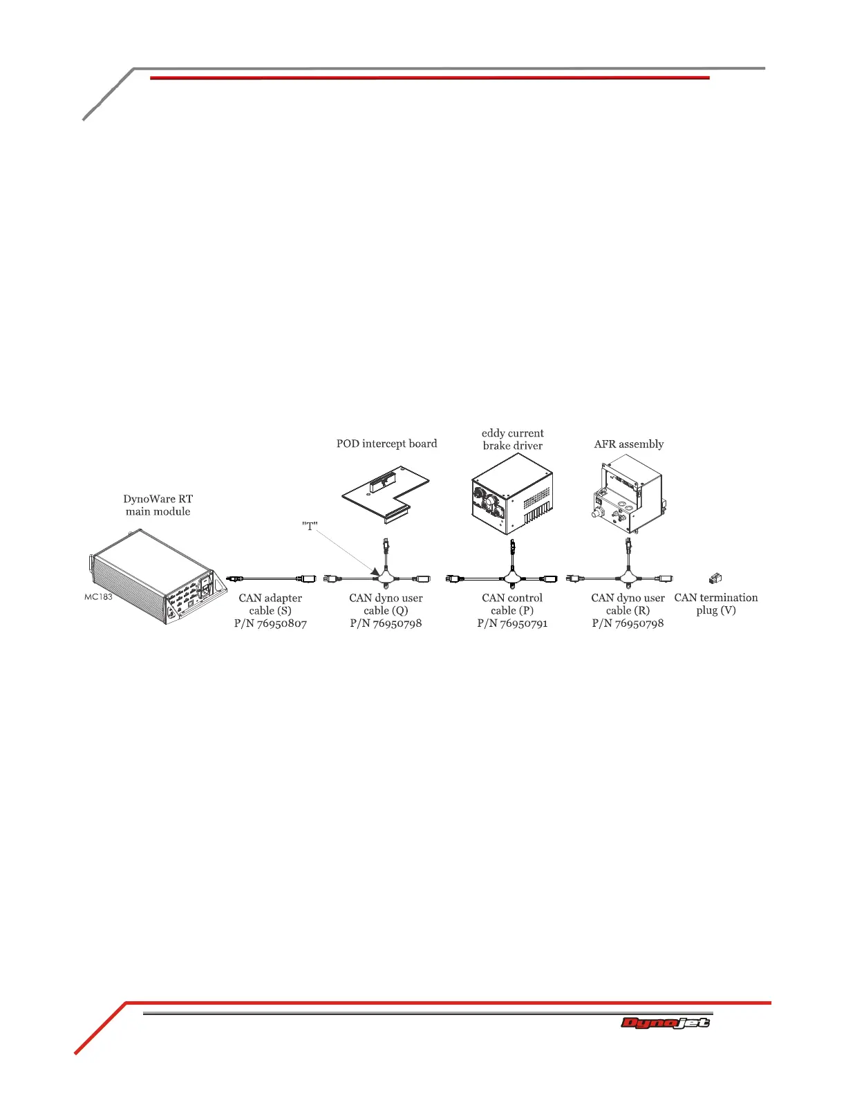
18 Attach the CAN adapter cable (S) to C on the back of the DynoWare RT main
module.
19 Attach the CAN dyno user cable (Q) to the CAN adapter cable (S) and route to the
POD intercept board. Attach the CAN dyno user cable (Q) to the POD intercept
board.
20 Attach the CAN control cable (P) to the “T” on the CAN dyno user cable (Q) and
route to the eddy current brake driver. Attach the CAN control cable (P) to the
eddy current brake driver.
21 Attach the CAN dyno user cable (R) to the “T” on the CAN control cable (P) and
route to the AFR assembly. Attach the CAN dyno user cable (R) to the AFR
assembly.
Note: The AFR assembly is an optional accessory.
22 Insert the CAN termination plug (V) in the CAN dyno user cable (R).
Note: If you do not have an eddy current brake and/or AFR assembly, insert the
CAN termination plug (V) at the end of your CAN network cable chain.
Figure 2-28: CAN Network Cable Configuration
 Loading...