4 Wiring with
4.6 High-speed counters, -DA, -DC
102 Operating instructions 05/10 MN05013003Z-EN www.eaton.com
4.6.1.5 Value range
The counter relay counts between 4 and 1000 [Hz].
Parameter display in RUN mode:
4.6.1.6 Retention
Setting retention on the frequency counter serves no purpose since the
frequency is continuously remeasured.
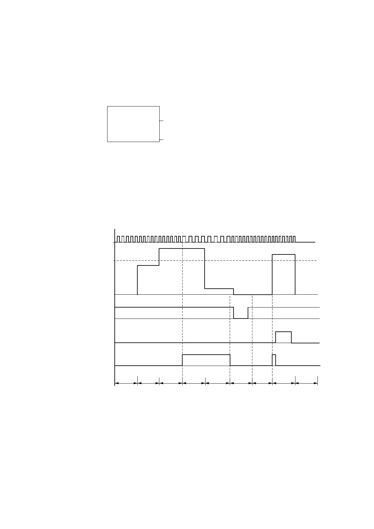
4.6.1.7 Function of the frequency counter
Figure 56: Signal diagram of frequency counter
1: counter input I3 or I4
2: upper setpoint
3: enable coil CC…
4: reset coil RC…
5: contact (N/O contact) C… upper setpoint value reached.
tg
: gate time for the frequency measurement
• Range A: the counter is enabled. After a frequency above the setpoint was measured for the first time,
contact C15 (C16) switches.
• Range B: If the actual value falls below the setpoint, the contact is reset. The removal of the enable
signal resets the actual value to zero.
Current setpoint, constant (0246)
# Contact has not switched.
â Contact has switched.
Actual value (00153)
1
2
3
t
g
t
g
t
g
t
g
t
g
t
g
t
g
t
g
4
5
t
g
A
BC
D

 Loading...


