4 Wiring with
4.12 Year Time Switch
138 Operating instructions 05/10 MN05013003Z-EN www.eaton.com
4.12.2 Behavior in the event of a power failure
The time and date are backed up in the event of a power supply failure and
continue to run. This means that it will continue to run in the event of a
power failure, although the time switch relays will not switch. The contacts
are kept open when de-energized. Refer to → Section "8.3 Technical data“,
page 211, for information on the buffer time.
4.12.3 Wiring of a year time switch
You can only include a year time switch in your circuit diagram as a Y..
contact.
The coils and contacts have the following meanings:
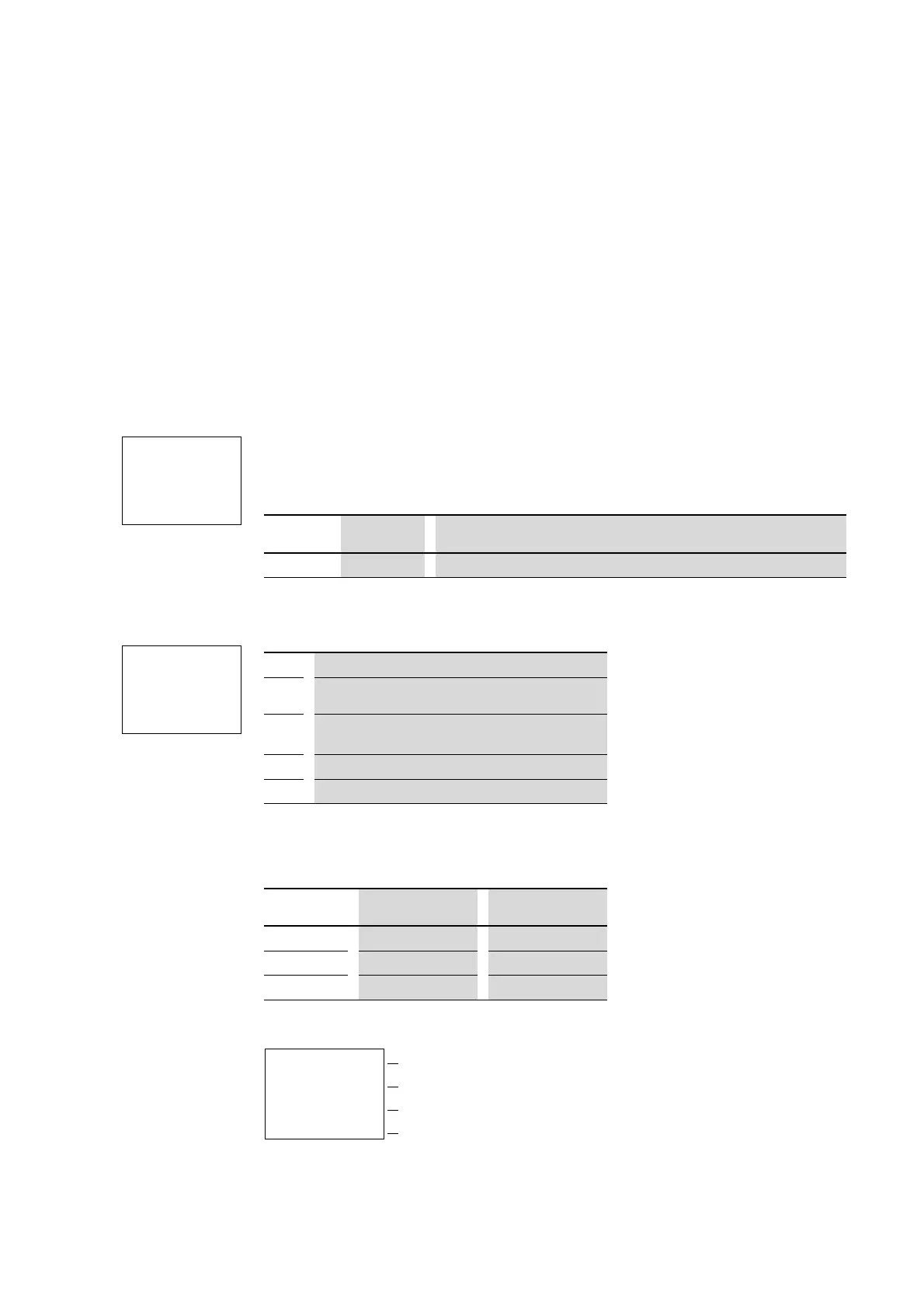
4.12.4 Parameter display and parameter set for year time switch
The parameter display for a year time switch is used to modify the closing
delay, the break time and the enable of the parameter display.
Table 15: On and off times
Parameter display in RUN mode:
→
The clock module integrated in easy works within the date
range 2001-01-01 to 2099-12-31
Y1u------ÄQ1
Y2k
Ö1-Y3----ÄQ2
Contact Coil
Y1 to Y8 Contact of the year time switch
Y1 A +
ON --.--.--
OFF --.--.--
Y1 Year time switch function relay 1
A,B,
C,D
Time switch channels
+ • + appears in the PARAMETER menu.
•
- does not appear in the PARAMETER menu
ON On date: day, month, year (two-digit 2010 = 10)
OFF Off date: day, month, year (two-digit 2011 = 11)
Parameters Meaning Meaningful values
xx.--.00 Date, day 01 to 31
--.xx.00 Month 01 to 12
--.--.00 Year, two-digit 00 to 99
Selected channel
Closing delay
Off time
# Contact has not switched.
â Contact has switched.
Y1 A +
ON 04.01.01
OFF 04.12.31
â

 Loading...


