2 Installation
2.5 Connecting inputs
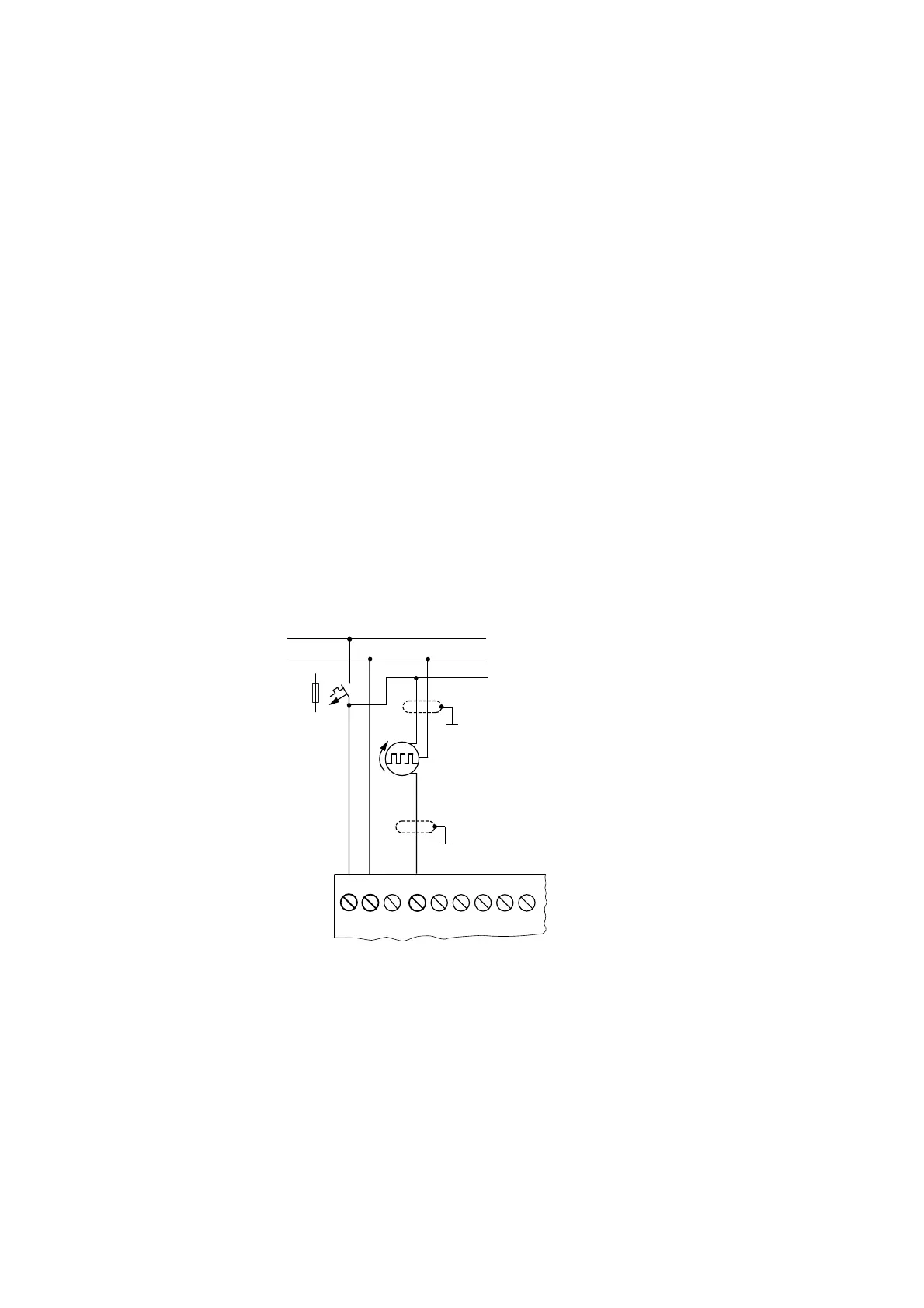
Operating instructions 05/10 MN05013003Z-EN www.eaton.com 41
2.5.4 Connecting high-speed counters and frequency generators
High-speed counter signals and frequencies on the easy-DA and easy-DA can
be counted accurately on inputs I1 to I4 independently of the cycle time.
These inputs are permanently assigned to counters.
The following applies:
• I1 = C13 high-speed up/down counter
• I2 = C14 high-speed up/down counter
• I3 = C15 frequency counter
• I4 = C16 frequency counter
Pulse shape of count signals:
easy processes square wave signals.
Mark-to-space ratio of count signals:We recommend a mark-to-space ratio of
1:1.
If this is not the case:The minimum pulse or pause duration is 0.5 ms.
t
min
= 0.5 x (1/f
max
)
t
min
= minimum time of the pulse or pause duration
f
max
= maximum count frequency (1 kHz)
Figure 26: Connecting high-speed counters and frequency generators
→
Inputs that are used as high-speed counter inputs should not be
used in the circuit diagram as contacts. If the counter frequency
is high:
Not all the signals of the high-speed counter can be monitored
for processing in the circuit diagram. easy will only process a
randomly logged state.
0 V
0 V
...V
L01 –
F1
L01 +
I1
I2 I3
I4 I5
I6
L02 +
24 V H

 Loading...


