4 Wiring with
4.2 Working with contacts and relays
72 Operating instructions 05/10 MN05013003Z-EN www.eaton.com
4.2.6 Coil Functions
You can set the coil function to determine the switching behavior of relay
coils. The following coil functions are available for relays Q, M, S, D, “:”:
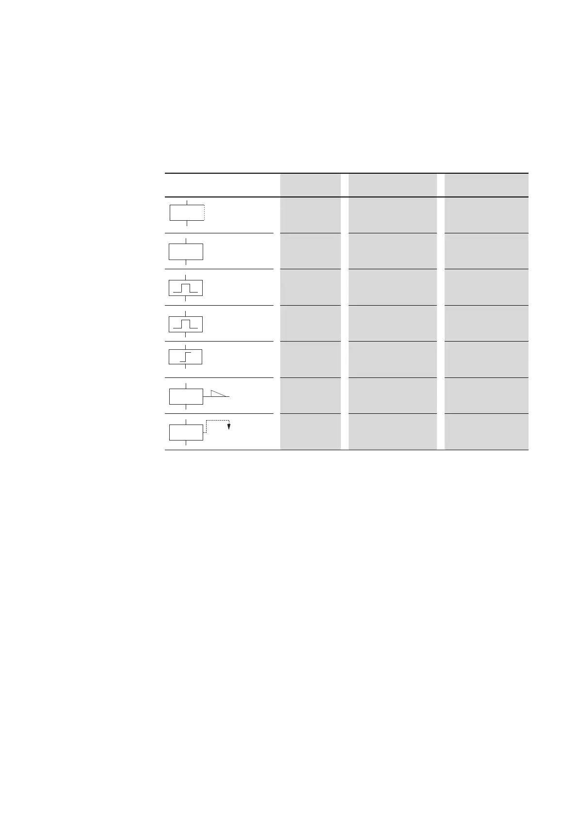
Table 8: Coil Function
Marker relays M and N are used as a flag. The S relay can be used as the
output of an expansion unit or as a marker if no expansion unit is connected.
The only difference between them and the output relay Q is that they have
no output terminals.
Circuit diagram display easy display Coil function Example
Ä Contactor Function ÄQ1, ÄD2, ÄS4, Ä:1,
ÄM7
Å Contactor function with
negated result
ÅQ1, ÅD2, ÅS4
è Cycle pulse on falling
edge
èQ3, èM4, èD8, èS7
È Cycle pulse on rising edge ÈQ4, ÈM5, ÈD7, ÈS3
ä Surge function äQ3, äM4, äD8, äS7
S Latch (set) SQ8, SM2, SD3, SS4
R Reset (unlatching) RQ4, RM5, RD7, RS3
→
The coil functions of the function relays are described in the
descriptions for the appropriate relays.
→
The coil functions Ä, Å, è, È, (contactor, contactor negated, cycle
pulse negative, rising edge) must only be used once for each
relay coil. The last coil in the circuit diagram determines the
status of the relay.
When controlling a contactor or relay, the control coil is only
present once. If you are creating parallel circuits, use Set, Reset
as a coil function.

 Loading...


