4 Wiring with
4.2 Working with contacts and relays
74 Operating instructions 05/10 MN05013003Z-EN www.eaton.com
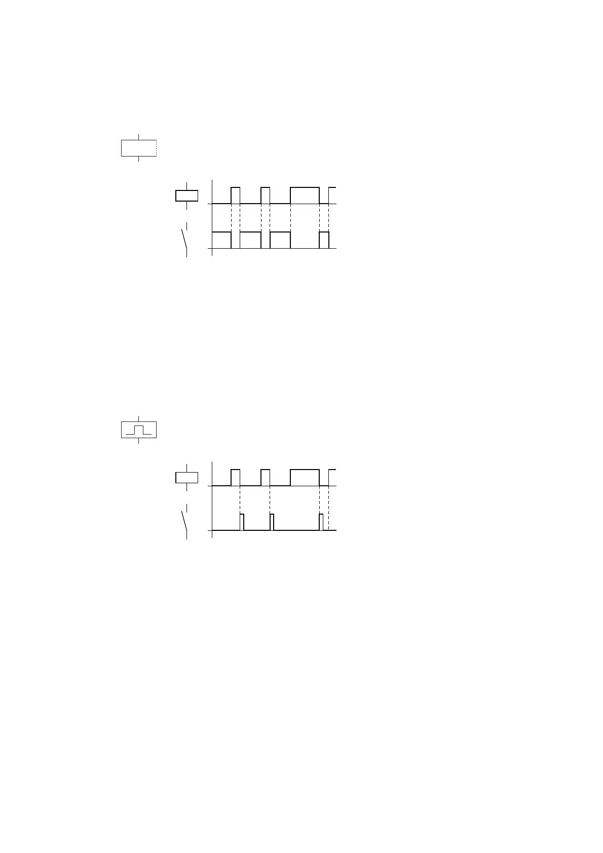
4.2.6.3 Contactor function with negated result (inverse contactor function) Å
The output signal is simply an inversion of the input signal; the relay operates
like a contactor with contacts that have been negated. If the coil is triggered
with the state 1, the coil switches its N/O contacts to the state 0.
Figure 41: Signal diagram, inverted contactor function
Representation in easy:
• Output relays Q:
ÅQ1 to ÅQ8 (depending on type)
• Markers M, N:
ÅM1 to ÅM16, ÅN1 to ÅN16
• Function relays (Text) D:
ÅD1 to ÅD16
• Output relays S:
ÅS1 to ÅS8
• Jumps:
Å:1 to Å:8
4.2.6.4 Falling edge evaluation (cycle pulse) è
This function is used if the coil is only meant to switch on a falling edge. With
a drop-out in the coil state from 1 to 0, the coil switches its N/O contacts to
the 1 state for one cycle.
Figure 42: Signal diagram, cycle pulse on falling edge
Representation in easy:
• Markers M, N:
èM1 to èM16, èN1 to èN16
• Jumps:
è:1 to è:8
→
Physical outputs should not be used as a cycle pulse is
generated.

 Loading...


