2 I/O modules EU5E-SWD…
2.9 Digital module EU5E-SWD-4D4D-R
40 SmartWire-DT module IP20 01/20 MN05006001Z-EN www.eaton.com
Byte 1: State of digital inputs/outputs
The Stat_Qx status bits indicate the outputs' state. This means that if out-
puts have been configured as "retentive," the outputs' state can be identified
in the user program after communications are restored or when the PLC
starts.
2.9.7.2 Outputs
Byte 0: outputs
The way the outputs are driven will depend on the selected configuration.
Output configured as retentive:
Driving will be based on a 2-bit combination for setting and resetting.
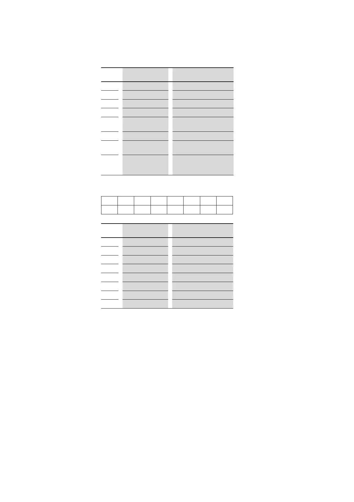
Bit Designation Description
0 Not used –
1
Not used –
2
Not used –
3
Not used –
4
DIAG 0: no diagnostic alarm
1: Diagnostic alarm
5
Not used –
6
PRSNT 0: Module not available
1: Module available
7
SUBST 0: Configured module present
1: universal module M22-SWD-
NOP(C) present
76543210
––––I3I2I1I0
Bit
Designation Description
0 I0 Status input I0
1
I1 Status input I1
2
I2 Status input I2
3
I3 Status input I3
4
Stat_Q0 Output Q0 status
5
Stat_Q1 Output Q1 status
6
Stat_Q2 Output Q2 status
7
Stat_Q3 Output Q3 status
→
This is the logical driving state.
If an output is being driven but is switched off by the output
stage due to a short-circuit / overload situation, or if the 24 V
power for the outputs is missing, a "1" will still be returned.
 Loading...


