WaveRIDER 165
Chip Detection
Chip wave data is determined in the same manner as the solder wave. The presence of
a chip wave is automatically detected when two solder contact points are detected on
sensors A or B, or four solder contact points measured by sensor “C” / Speed Sensor.
The solder contact time between the chip and solder wave for the C sensor must be
greater than 1.0 seconds to be counted as separate wave contacts. If less than 1.0
seconds, the multiple solder contacts are considered “noise” or contact bounce and are
counted as one wave contact rather than two.
In addition, as the distance between the chip and solder wave gets larger, the time
between the C sensor leaving the solder wave and the Speed sensor hitting the chip
wave must also be less the 1.0 seconds. If not, these two solder contacts will be seen
as one wave for the same reasons stated above.
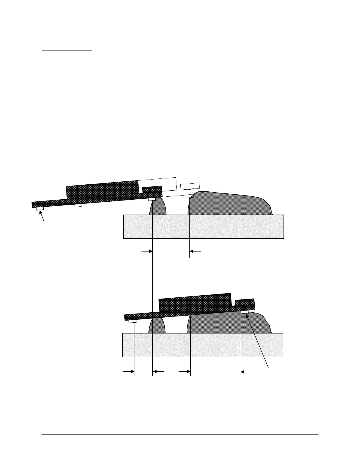
Figure C- 3 illustrates the interaction between the two waves and the WaveRIDER pallet
sensors as described above.
Figure C- 3: Chip/Solder Wave vs. WaveRIDER Pallet Sensors
Chip to Solder Wave Separation
Travel time between waves must be greater
than 1.0 seconds.
C Sensor just exits the
Solder Wave
Speed Sensor
C to Speed Sensor Separation
Travel time between C just exiting the solder
wave and Speed sensor entering chip wave
must be greater than 1.0 seconds.
Solder Wave
Contact Length
 Loading...