5. Functions
Logic functions are used to define an extended behaviour of the display depending on the channel
input values.
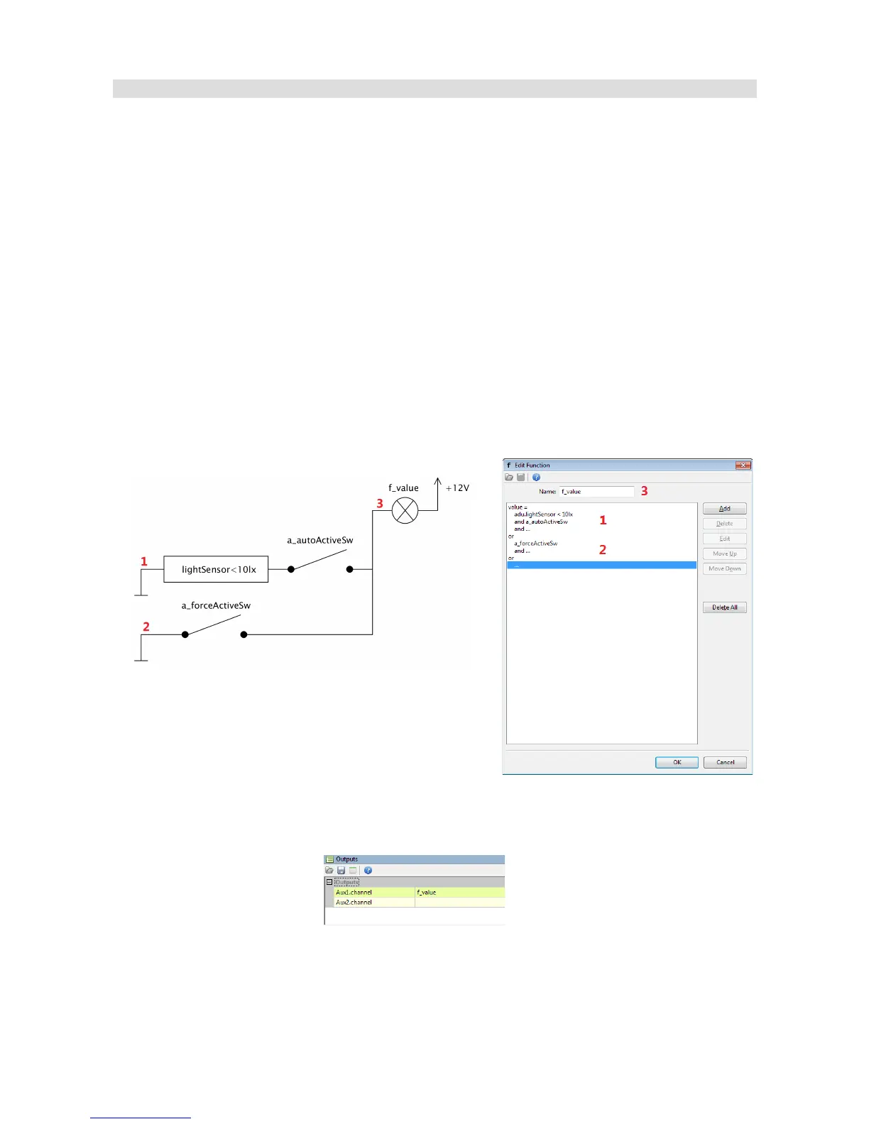
Example #1: Controlling a dome light using a light sensor.
The dome light will turn on when at least one of the conditions is met:
– when it is dark and automatic mode is active (the a_autoActiveSw switch is on)
– when manual lighting mode is active (the a_forceActiveSw switch is on)
Both switches are connected to analogue inputs of the device.
An analogy comparing a logic function to an electrical diagram is shown below. A logic function will
be true if at least one of the branches is true. A branch, in turn, is true when all operations in its
branch are true.
Now that the logic is done, assign the Aux1 output so that it can be controlled with f_value:
Page 107/137
 Loading...