Installation
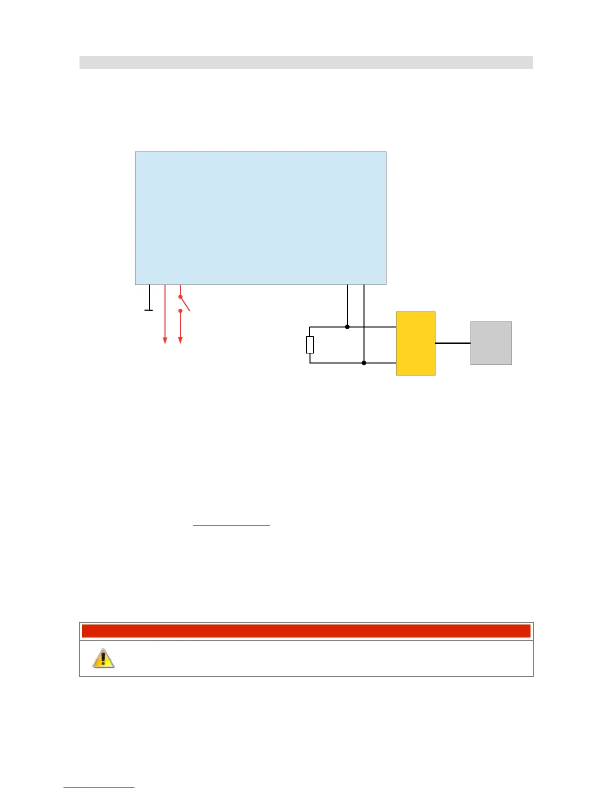
To start the device and communicate with a PC, connect the device's power supply and the
USB2CAN interface to CAN1.
This bus has a constant speed of 1Mbps and one of its functions is communication with a PC.
The above figure shows the minimum connections required to power the device and enable
communication with a PC.
The ADU is programmed through a USB to CAN adapter. Any of these three devices may be used
to enable communication between PC and ADU:
– Ecumaster USBtoCAN (www.ecumaster.com)
– Peak Systems PCAN USB (www.peak-system.com)
– Kvaser USBcan (www.kvaser.com)
All of these interfaces are equipped with DB9 connectors, where CANL and CANH signals are on
terminals No. 2 and No. 7 respectively.
The diagram also includes a 120Ohm terminator, which is necessary for the correct operation of
the bus (for more information about the terminators see the CAN-BUS section).
IMPORTANT !
Do not connect the +5V output from the CAN interface to +5V ADU!
Page 13/137
ADU
3 CAN1.H
4 CAN1.L
23 Ground
12 Battery
11 Switched 12V
CAN BUS
120 Ohm
USBtoCAN
2
7
USB
PC