Connector
A single 35 position AMPSEAL connector on the rear of the display is used to connect the power
supply, CAN buses and additional sensors or buttons.
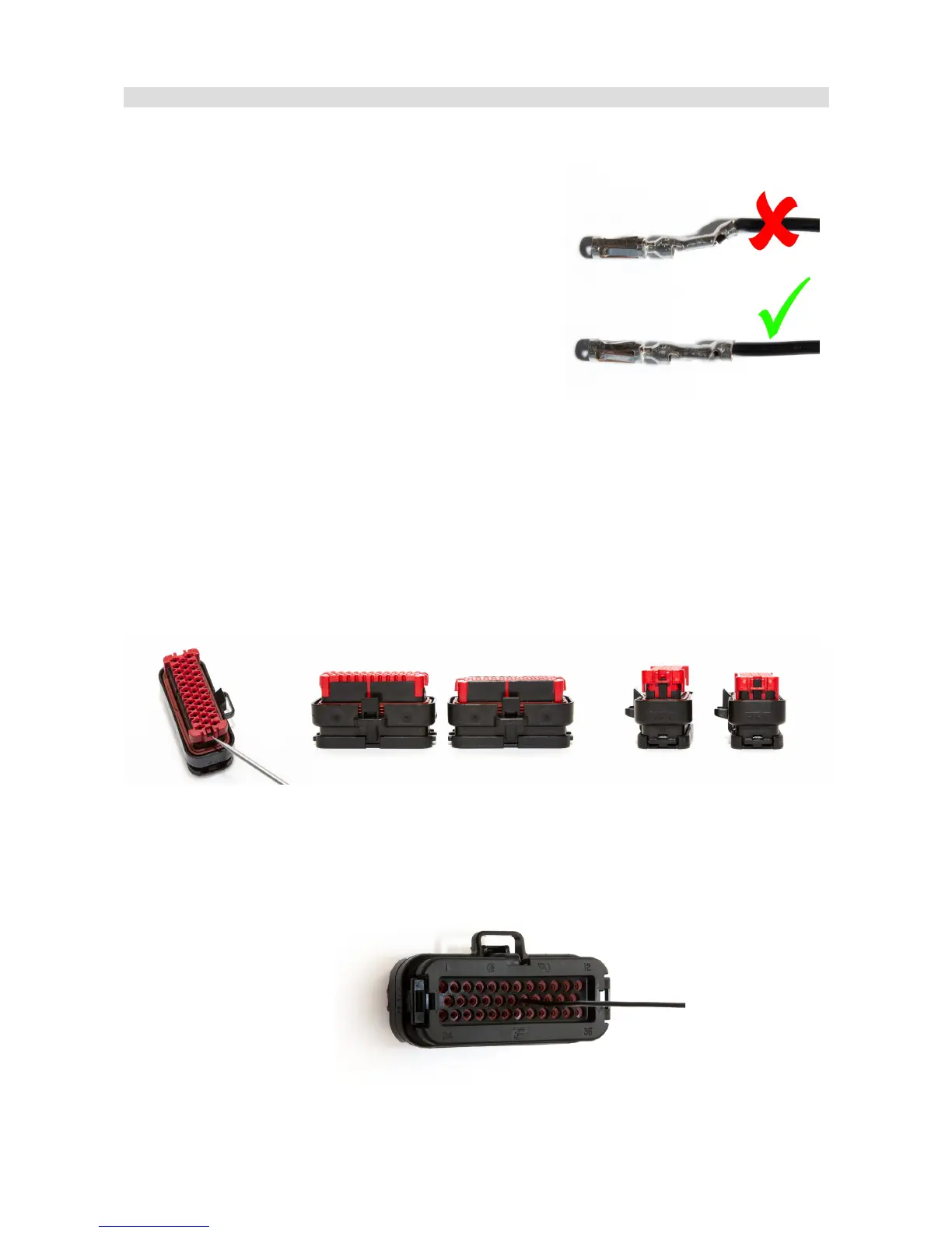
A connector and terminals are included with the device. In
order to crimp the terminals, use an appropriate crimping
tool. We do not recommend soldering the wire to the
terminal! If replacement terminals are required, the part
number is AMP 770520-1.
It is critical that terminals are crimped correctly. This type of
connector is very sensitive to the straightness of the
terminal. If excessive force or improper tooling is used, the
terminal will deform and will be difficult to install or remove. The portion of the crimp that supports
the insulation must be circular and of a diameter equal to or smaller than the terminal.
In order to insert or remove terminals, the red terminal lock must be released to the halfway
position, but not removed completely. To eject the red terminal lock, pry the two black latches using
a sharp tool and gently pull the lock. The lock should extend by about 0.5 cm. The teeth prevent
total removal of the red lock from the connector housing. In this position the connector housing is
ready to have terminals inserted or removed.
Terminals should be inserted from the back side of the connector. The mat seal is designed to
allow for the insertion of terminals. Do not attempt to disassemble the back of the connector
housing.
Page 9/137