• Channel #0 - voltage value at input A1 will be sent as one from the range of 0, 1, 2, 3, 4, 5
(i.e. in volts, but without the fractional part).
• Channel #1 - voltage value at input 1A will be sent as a number from the range 0..5000 (i.e.
in milivolts)
• Channel #2 -voltage value at input 1 A will be sent as a raw value from the ADC converter,
a number from the range ..1023
• Channel #3 - voltage value at input 1A will be sent as a number from the range 0..255
• Channel #4 – a constant value will be sent - 15 decimal
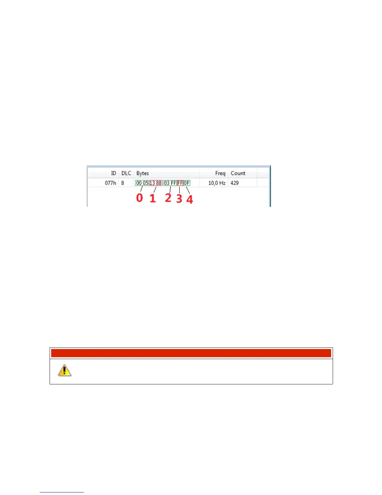
Below is a frame preview as seen in the ECUMASTER Light Client application. At the A1 analogue
input the voltage is exactly 5V. Channel #0 - Channel #5, respectively, as in the above example:
• Channel #0 - value 0x0005, i.e. 5 [V]
• Channel #1 - value 0x1388, i.e. 5000 [mV]
• Channel #2 - value 0x03FF, i.e. 1023 [adc]
• Channel #3 - value 0xFF, i.e. 255
• Channel #4 - value 0x0F, i.e. 15
(4) Selection of a bus, CAN ID, sending frequency.
Select a sending frequency ranging from 1..100 Hz.
Select a CAN ID. Make sure you don’t collide with other communications in the network.
WARNING!
It is not permitted for two devices in the CAN network to send frames of
the same CAN ID !
Page 99/137