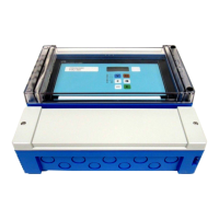
The "relays/controls" menu
81
5.2 The "pump control N" submenu - standard
(N = 1 or 2)
!
Note!
Depending on the order code of the instrument, different functionalities can be configured for the
pump control. The order code of the instrument can be found on the nameplate and in the operating
menu at "system information/device information".
This chapter is only valid for instruments with standard pump control
(FMU90-*1********** and FMU90-*2**********).
For the enhanced pump control see chapter 5.3
(FMU90-*3********** and FMU90-*4**********).
!
Note!
The "pump control N" submenus are only present if "pump control" has been selected in "device
properties/operating parameters/controls".
5.2.1 Basic principles
Switch points
The pump control is used to start or stop pumps depending on the measured level. To do this, a
switch-on point and a switch-off point is defined for each pump. Additionally, a relay is assigned to
the pump and the switching is performed by this relay.
Two cases can be distinguished for the swichting behaviour of this relay:
a. Switch-on point > Switch-off point
The pump is switched on if the level rises above the switch-on point (A). It is switched off if
the level drops below the switch-off point (B).
Example: Emptying of a flood control reservoir.
L00-FMU90xxx-19-00-00-yy-051
A: switch-on point; B: switch-off point; C: pump on; D: pump off
b. Switch-on point < Switch-off point
The pump is switched on if the level drops below the switch-on point (A). It is switched off if
the level rises above the switch-off point (B).
Example: Filling of a storage vessel
L
A
B
t
t
C
D

 Loading...


