Rev. A Handling and Maintenance 3-15
TM-U950/U950P Technical Manual
Lubrication schedule: When the printer is overhauled or after every 5 million print lines.
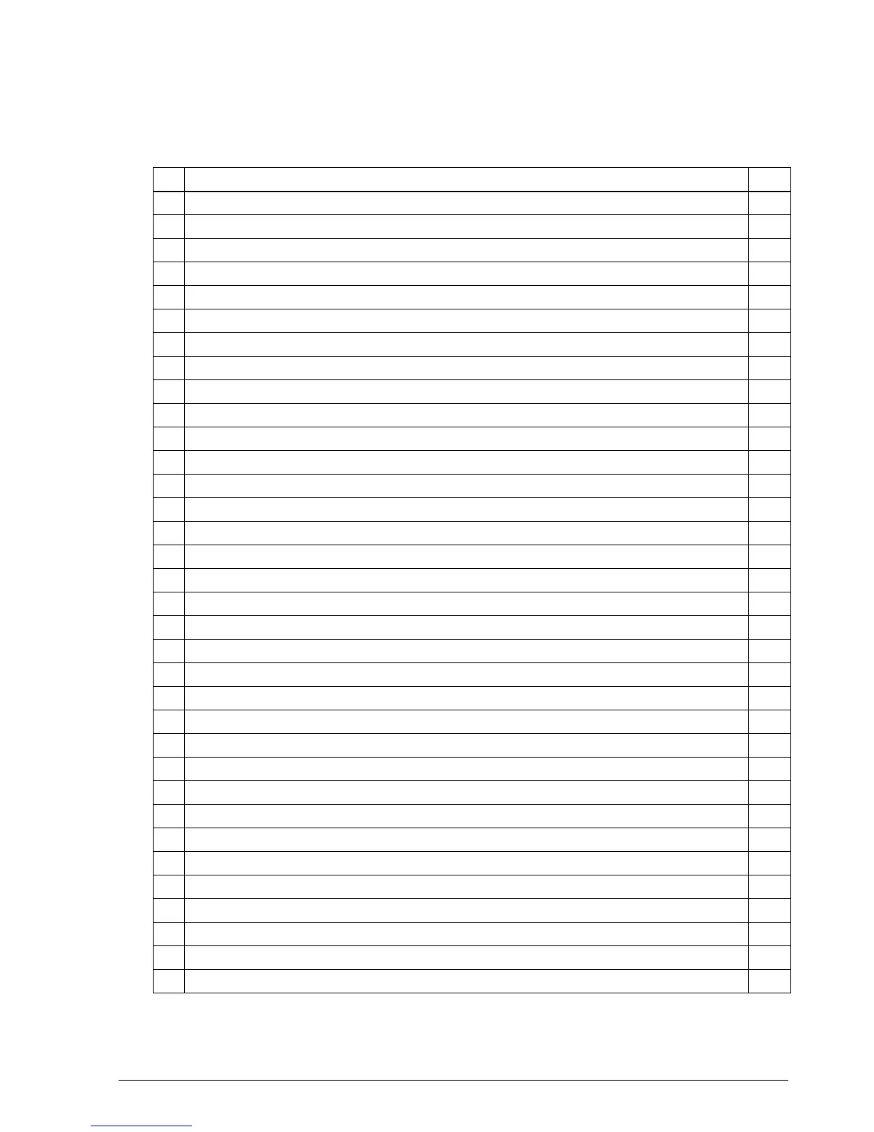
Table 3-2. Lubrication Points for Printer Mechanism Unit (for printers without an MICR reader)
No. Lubrication Point (See lubrication point diagrams at end of Chapter 6 (Appendix) Type
1 Roller-sub paper feed assembly mounting U-cut notches (four) of paper guide-upper G-36
2 Roller mounting portions of sub paper hold roller G-36
3 Shaft of paper guide-lower G-15
4 Lever-stamp sliding portions (three) of paper guide-lower G-36
5 Lever-stamp drive hooding portion of lever-stamp G-15
6 Iron core notch G-15
7 Shaft of cutter motor mount plate sub assembly G-36
8 Bigger wheel of deceleration gear A G-36
9 Two holes of each paper hold roller G-36
10 Two shafts of cutter frame sub assembly G-36
11 Center wheel of cutter drive shaft sub assembly G-36
12 Both wheel of deceleration gear B G-36
13 Bigger wheel of deceleration gear A G-36
14 Cutter slider contact portion of frame-cutter blade receiving assembly G-36
15 Circuit pattern on cutter slider assembly G-20
16 Shaft of pulley base-carriage transmission assembly G-36
17 Oil ring O-2
18 Two shafts of frame-carriage assembly G-15
19 Carriage catching surface (above) of frame-carriage assembly (five) G-19
20 Carriage catching whole surface (below) of frame-carriage assembly G-19
21 Five shafts of frame-carriage assembly G-36
22 Wheel of carriage feed pulley G-36
23 Ribbon feed transmission gear G-36
24 Gear-ribbon feed G-36
25 Two shafts of roller-slip paper hold assembly G-15
26 Four dowels of frame-inner G-15
27 Lever-sub slip paper feed shaft contact portion with roller-sub slip paper feed G-15
28 Iron core notch G-15
29 Contact portion of form stopper and lever-sub slip paper feed shaft G-15
30 Contact portion of J/S changeover solenoid mount plate and J/S changeover solenoid G-15
31 Shaft of frame-paper take-up sub assembly G-36
32 Two U-cut notches of frame-paper take-up sub assembly G-36
33 Paper take-up gear contact portion with Paper take-up spring G-36
34 External surface of paper take-up spring G-36
CONFIDENTIAL