Rev. A Disassembly, Assembly, and Adjustments 5-23
TM-U950/U950P Technical Manual
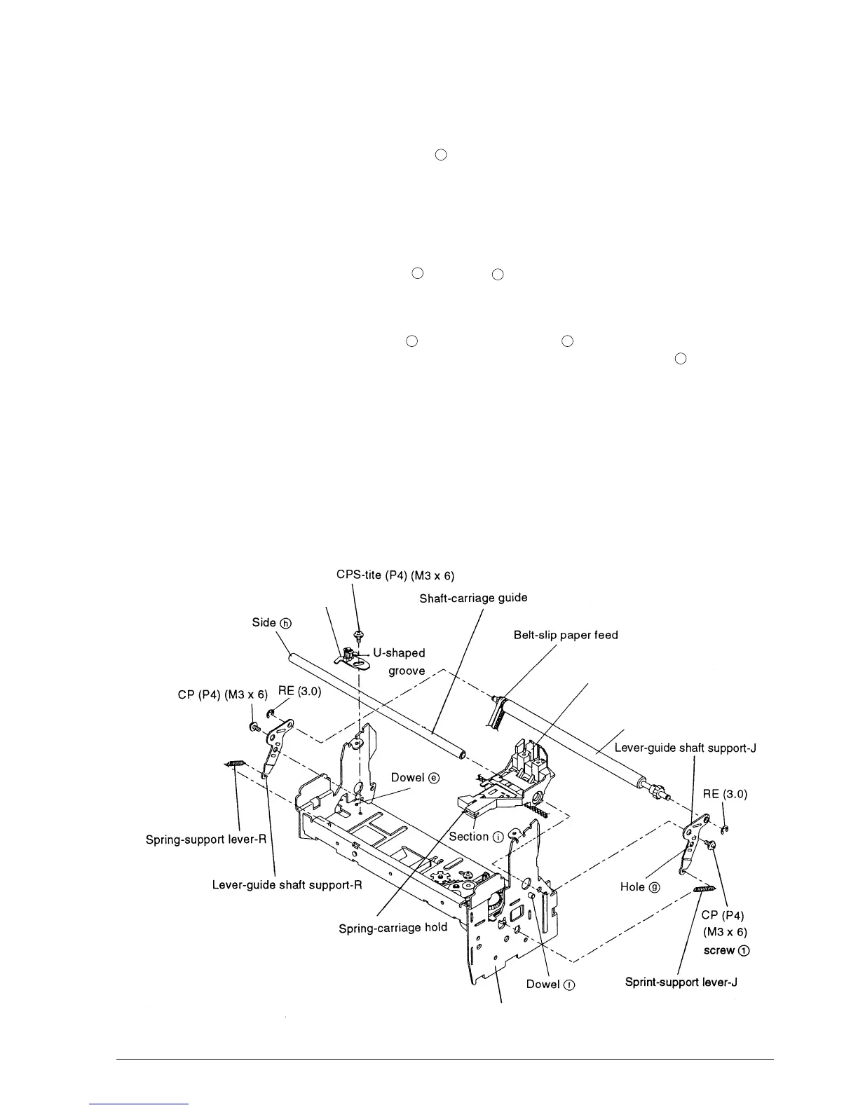
Sub-assembly L-(1)
5. Align the U-shaped groove with dowel and mount the pulley base-carriage transmission
assembly. Provisionally tighten the screw. (Final tightening is in carriage transmission belt
tension adjustment on page 5-56.)
6.* Mount the lever-guide shaft support-J on the roller-slip paper hold assembly and fasten it
with the RE.
7. Align the resulting part with dowel and hole and position the parts on the frame-
carriage assembly.
8. Pass the shaft-carriage guide through the carriage-head assembly and then through the
frame-carriage assembly from side . Then tighten screw in the illustration. The spring-
carriage hold must come below the frame and lock with the frame at section of the
carriage.
9. Engage the belt of the carriage-head assembly on the pulley-carriage transmission and the
carriage feed pulley.
10. Engage the belt-slip paper feed on the roller-slip paper hold assembly.
11. Attach the lever-guide shaft support-R and fasten it with the screw and RE.
12. Attach the support lever springs J (long) and R (short).
e
f
g
h
1
i
Frame-carriage assembly
Roller-slip paper hold assembly
Carriage-head assembly
Pulley base-carriage
transmission assembly
CONFIDENTIAL