Rev. A Disassembly, Assembly, and Adjustments 5-45
TM-U950/U950P Technical Manual
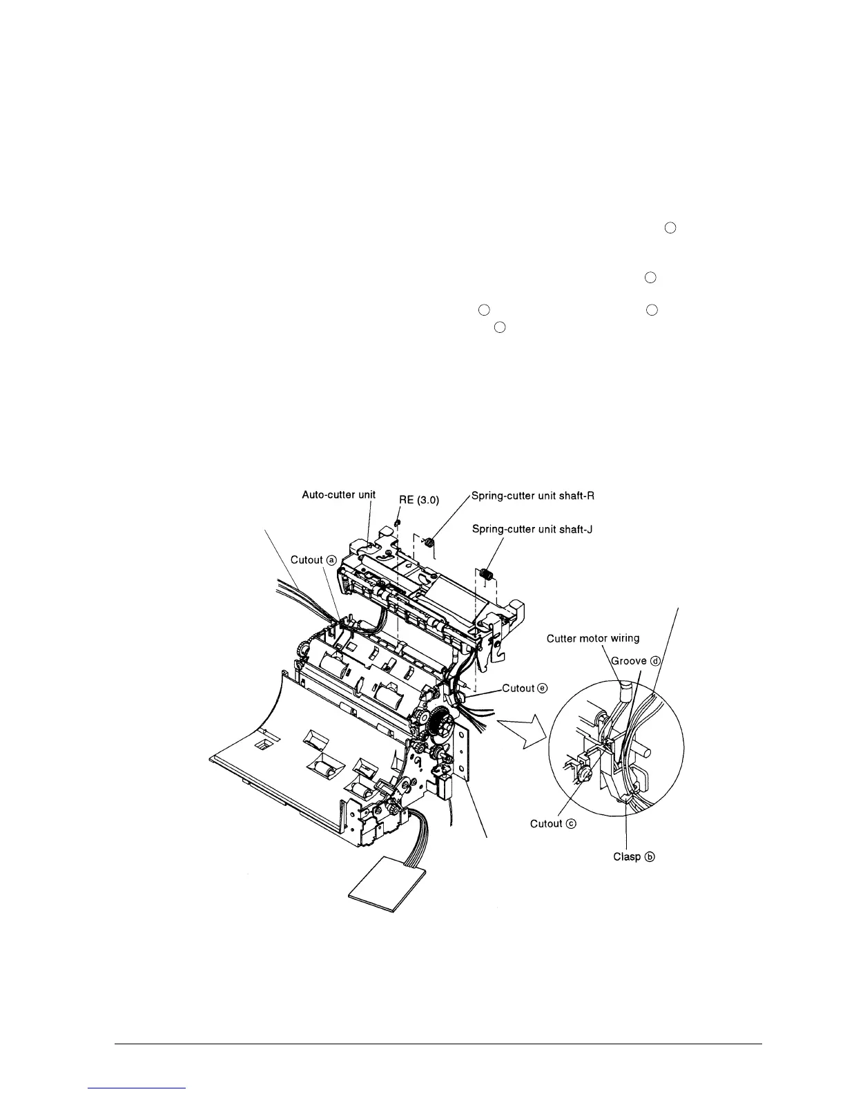
Main Assembly 1-5: Attachment of Auto-cutter Unit
1. Place the spring-cutter unit shaft-R onto the shaft of the auto-cutter unit with the short
end first.
2. Place the spring-cutter unit shaft-J in the same way.
3. Thread the wiring from the contact pin holder sub-assembly through cutout to the
outside.
4. Thread the wiring from the detector-slip ejection assembly through clasp .
5. Thread the cutter motor wiring through cutout and then along groove . The two
protective tubes should not protrude from cutout .
6. Mount the auto-cutter unit on the frame-main sassembly and engage the cutter unit shaft
springs J and R. Secure it with the RE.
✔
Checkpoint
Make sure that the spring-cutter unit shaft-J is not caught in the detector-slip ejection
assembly wiring.
a
b
c
d
c
Connect pin holder sub-assembly wiring
Detector-slip ejection assembly wiring
Frame-main assembly
CONFIDENTIAL
 Loading...


