1-18 Features and General Specifications Rev. A
Drawer kick-out connector (modular connector)
Pulse specified by ESC p command is output to this connector. The host can confirm the status of
the input signal by using the DLE EOT, ESC u, GR r, or GS a (ASB) commands.
Connector type:
Printer side 52065-6615 (Molex) or equivalent
User side 6-position 6-contact (RJ12 telephone jack)
(*1) Drawer kick-out drive signal
The signal specified by the ESC p command is output from pins 2 and 5 of the connector.
Output voltage: Approx. 24 V
Output current: 1 A max.
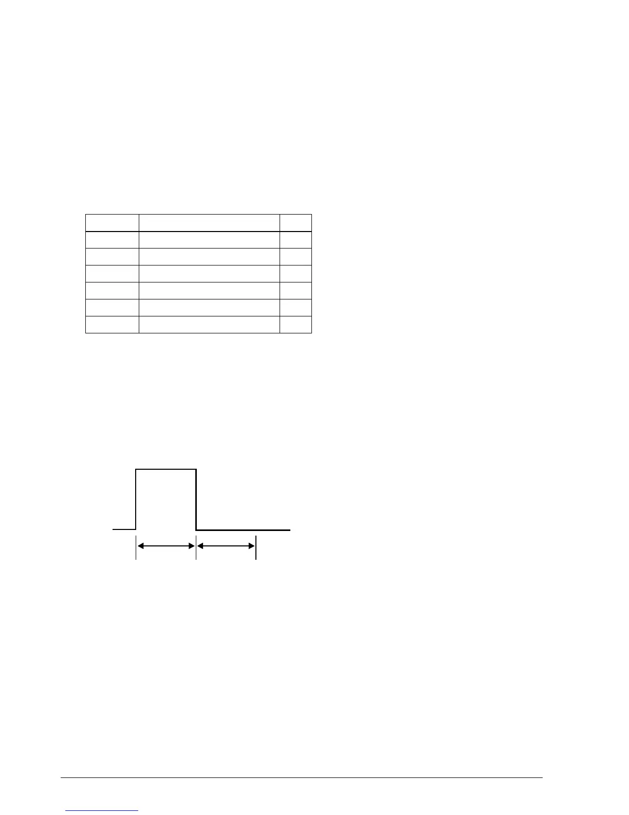
Output waveform: The waveform of the signal at pins 2 and 5 is shown in
Figure 1-15. (The ON time n1 and OFF time n2 are
determined by the ESC p command.)
(*2) Drawer open/close signal
The host computer can check the drawer open/close status with the DLE EOT, ESC u, GR r, or
GS a (ASB) commands.
Input signal level (connector pin 3)
Low = 0 to 0.8 V
High = 2 to 5 V
Table 1-5. Drawer Kick-out Connector Pin Assignment
Pin number Signal name I/O
1Frame ground —
2 Drawer kick-out drive signal 1 (*1) O
3 Drawer open/close signal (*2) I
4 + 24 V —
5 Drawer kick-out drive signal 2 (*1) O
6 Signal ground —
n1 x 10ms n2 x 10ms
Figure 1-15. Drawer Kick-out Drive Signal Timing
CONFIDENTIAL