1-28 Features and General Specifications Rev. A
DIP switch settings for the TM-U950
(*) Effective when a direct connection customer display is connected to the DM-D connector of
the printer.
❏ When the interface connector pin 6 is used to reset the printer, the printer is reset at MARK
with the RS-232C level.
❏ When the interface connector pin 25 is used to reset the printer, the printer is reset at SPACE
with the RS-232C level, and is reset at high with the TTL level.
Notes
❏
DIP switches (excluding switches 1, 7, and 8 of switch bank 2) are effective only while the printer
power is turned on. If the DIP switch setting is changed after the printer power is turned on, the
change is not effective.
❏
If DIP switch 7 or 8 of the switch bank 2 is on while the printer power is turned on, the printer may be
reset, depending on the signal state. DIP switches should not be operated while the printer power is
turned on
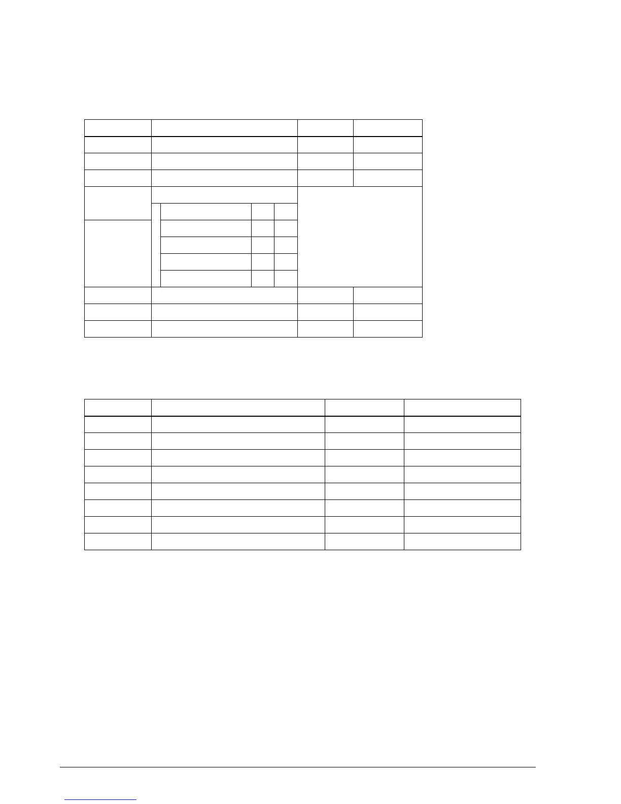
Table 1-9. DIP Switch Bank 1
Switch number Function ON OFF
1 Data word length 7 bit 8 bit
2 Parity check Yes No
3 Parity type Even Odd
4
Data transfer rate
Transfer rate (bps) 4 5
5
1200 On On
2400 Off On
4800 On Off
9600 Off Off
6 Connection of customer display (*) Connected Not connected
7 Data reception error handling Disregard Print “?”
8 Handshake XON/XOFFD DTR/DSR
Table 1-10. DIP Switch Bank 2
Switch number Function ON OFF
1 Automatic CR Always yes Always no
2 Reception buffer size 32 bytes 2048 bytes
3 Font selection (default setting) 9 x 9 7 x 9
4 Carriage speed (paper roll initial setting) Low speed High speed
5 Handshake operation (condition for BUSY) Receive buffer full Off line or receive buffer full
6 Internal use Fixed —
7 Interface pin 6 reset signal Used Not used
8 Interface pin 25 reset signal Used Not used
CONFIDENTIAL