Rev. A Mechanism Configuration and Operating Principles 2-27
TM-U950/U950P Technical Manual
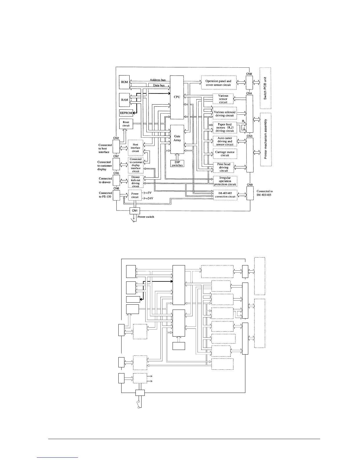
Figure 2-41. Block Diagram of TM-U950 Main Board
Figure 2-41a. Block Diagram of TM-U950P Main Board
Circuit Board Unit
Connected
to host
interface
Connected
to drawer
Connected
to PS-150
CNIF1
CN5
CN6
CN8
CN4
CN3
R
J
Host
interface
circuit
(parallel)
Drawer
kick-out
driving
circuit
Power
circuit
Address bus
Data bus
Operation panel and
cover sensor circuit
Various
sensor
circuit
Various solenoid
driving circuit
Paper feed
motors (R,J)
driving circuit
Auto cutter
driving and
sensor circuit
Carriage motor
circuit
Print head
driving
circuit
Irregular
operation
protection circuit
Power switch
+5V
+24V
CN1
EEPROM
RAM
ROM
CPU
Gate
Array
DIP
switches
Reset
circuit
Switch PCB unitPrinter mechanism assembly
Main Circuit Board Assembly
CONFIDENTIAL