EasyManua.ls Logo

Epson WF-C5790 - Page 329

Epson WF-C5790
608 pages
Print Icon
To Next Page IconTo Next Page
To Previous Page IconTo Previous Page
Loading...
EPSON WF-C5790/WF-C5790a/WF-C5710/ET-8700/WF-C5210/WF-C5290/WF-C5290a Revision A
Disassembly/assembly Disassembly/Reassembly Procedures 329
Confidential
DISASSEMBLY FLOWCHART
A1
E1
B1
F1
C1
Start
Rear Cover (Back)
(P. 330)
Start
ASF Front Cover
(P. 330)
Housing Left
(P. 331)
Ink Eject Cover
(P. 335)
Housing Right
(P. 335)
ADF/SCN Unit
(P. 336)
Housing Upper
(P. 336)
D1
A2
E2
B2
F2
C2
D2
A3
E3
B3
F3
C3
D3
F4
F5
F6
F7
Hinge Assy
(P. 337)
F8
Hinge Lower Cover
(P. 338)
F9
Cable Guide
(P. 338)
F10
Wireless Lan Module
(P. 331)
A4
PDL Board Assy
(P. 332)
B4
FAX Assy
(P. 333)
C4
SD Memory
(P. 334)
E5
E4
Extension Spring 11.11
(P. 339)
PS Ground Plate
(P. 340)
CR Scale
(P. 340)
F11
F12
F13
Main Board Assy
(P. 341)
F14
Wireless Lan Module
(P. 343)
F15
USB Interface Board*
(P. 328)
D4
F16
C H E C K
P O I N T
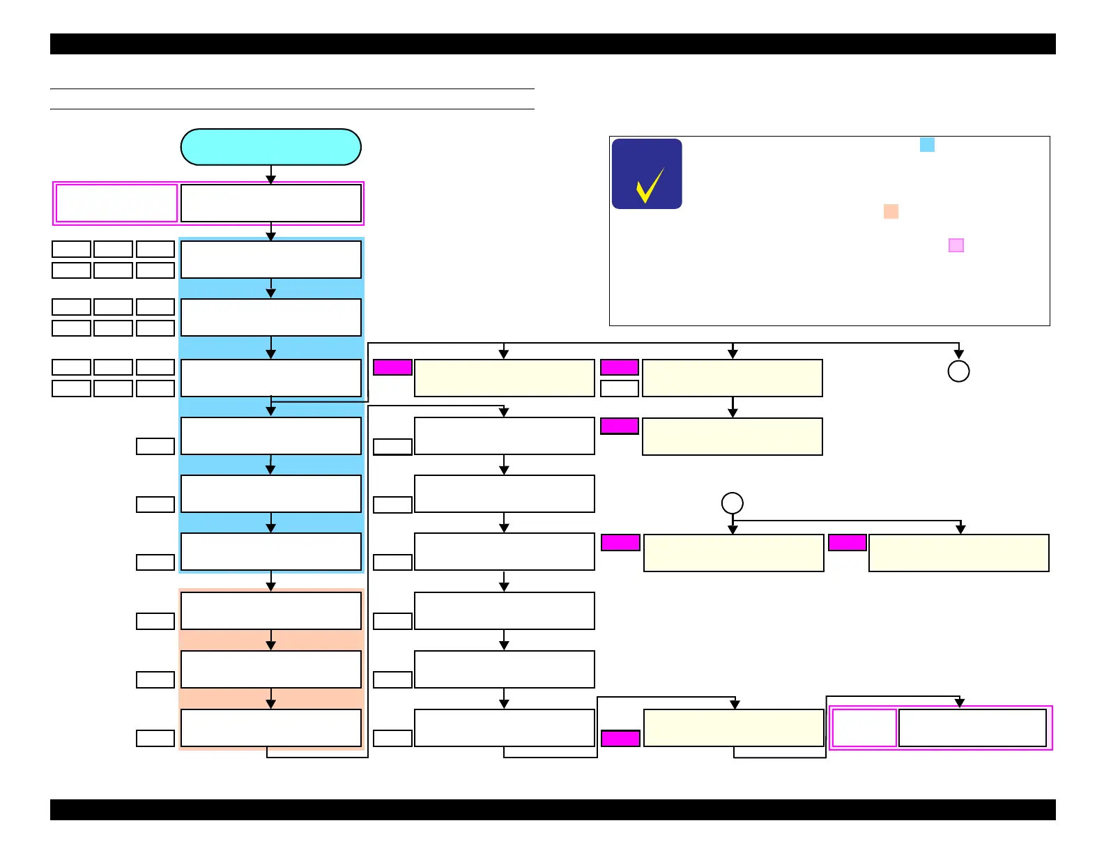
As for the procedure indicated by , refer to 6.2.4.4
Housing (WF-C5200 Series) (2) (p. 254)
in the case
of the WF-C5200 Series, and remove the parts from the
Rear Back Cover to the Housing Top.
The procedure indicated by is applicable only in the
WF-C5700 Series/ET-8700.
Implement the procedure indicated by when
replacing the Main Board Assy. See
Initial settings (p.
565)
and carry out EEPROM Data Copy (Backup)
beforehand and EEPROM Data Copy (Load) after
replacement.
a
a
* : Depending on the axial length of the driver, damage
may occur on the screw head due to oblique cutting.
In such a case, remove the USB Interface Board
after removing the Main Board Assy.
Preparation for
Dissembling
EEPROM Data Copy
(Back up) (P. 564)
After
assembling
EEPROM Data Copy
(Restore) (P. 564)
Main Board
(P. 344)

Table of Contents

Related product manuals