OPERATION ST100A Series Flow Meter
58 Fluid Components International LLC
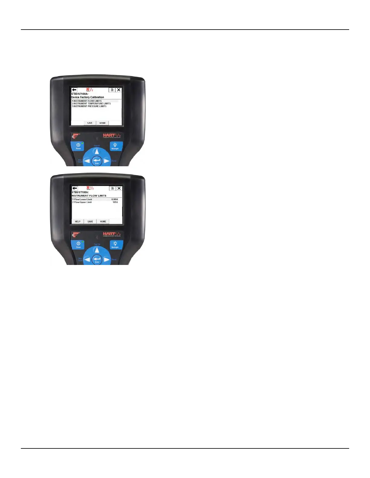
Device Factory Calibration Example (from Advance Setup
Device Setup)
The Device Factory Calibration function lets you review the limits that have been
set for the Flow, Temperature, and Pressure process parameters.

 Loading...


