Section 4: Using the Model 9500B — Load R and C Measurement 4.16-1
Final Width = 215mm
Descriptions assume 9500B/1100
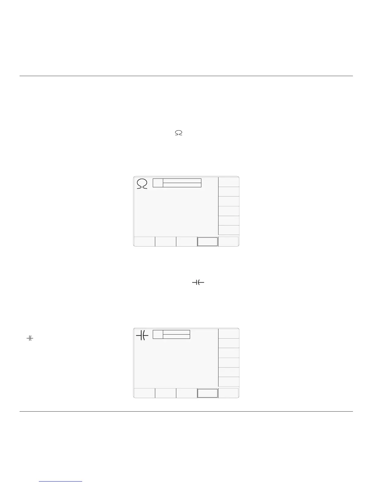
4.16.3.2 Load Capacitance Defaults
The Load Capacitance Measurement is
accessed by first pressing the 'Aux' key on the
right of the 'OSCILLOSCOPE CALIBRATOR'
panel, then pressing the
soft key at the
bottom of the screen.
Whenever the Load Capacitance screen is
opened, except on recovery from a standby
period, it will appear as follows (but also refer
to para 4.5.3.6):
4.16 Load Resistance and Capacitance Measurement
This sub-section is a guide to using the 9500B
to measure the resistive or capacitive load
presented by the channel inputs of a UUT
oscilloscope.
For those users who require more detailed
instructions for interconnections, and
manipulating the front panel controls, refer to
sub-sections 4.2, 4.3 and 4.4.
Section 4.16 is divided into the following sub-
sections:
4.16.1 Introduction .................................................. 4.16-1
4.16.2 Measurement Method ................................... 4.16-1
4.16.3 Default Settings ............................................ 4.16-1
4.16.3.1 Load Resistance Defaults ............. 4.16-1
4.16.3.2 Load Capacitance Defaults ........... 4.16-1
4.16.4 Menu Selections ........................................... 4.16-1
4.16.4.1 Load Resistance Menus ............... 4.16-1
4.16.4.2 Load Capacitance Menus ............. 4.16-1
4.16.4.3 Retained Channel Memory ........... 4.16-1
4.16.5 Measurement Operation ............................... 4.16-1
4.16.5.1 Bottom Screen Keys (Resistance) . 4.16-1
4.16.5.2 Bottom Screen Keys (Capacitance) 4.16-1
4.16.6 Use the 9500B to Measure the
Load Resistance or Load Capacitance .......... 4.16-2
4.16.6.1 Introduction .................................. 4.16-2
4.16.6.2 Interconnections ........................... 4.16-2
4.16.6.3 9500B and UUT Scope Setup ....... 4.16-2
4.16.6.4 Sequence of Operations
(Load Resistance) ........................ 4.16-2
4.16.6.5 Sequence of Operations
(Load Capacitance) ...................... 4.16-2
4.16.2 Measurement Method
UUT Oscilloscope input load resistance or
capacitance can be measured directly via any
active head.
With the 9500B 'Auxiliary' functions, and 'Ω'
or ' ' function selected, the load resistance or
capacitance presented by the UUT oscilloscope
input to the active head will be shown on the
screen. No triggers are provided.
4.16.1 Introduction 4.16.3 Default Settings
4.16.3.1 Load Resistance Defaults
The Load Resistance Measurement is accessed
by first pressing the 'Aux' key on the right of
the 'OSCILLOSCOPE CALIBRATOR' panel,
then pressing the soft key at the bottom of
the screen.
Whenever the Load Resistance screen is
opened, except on recovery from a standby
period, it will appear as follows (but also refer
to para 4.5.3.6):
TODAY'S DATE TIME
OFF
READING CH1 1MΩ
Load Resistance
SIGNAL
CHANNEL
Ø.ØØØ Ω
TODAY'S DATE TIME
OFF
READING CH1
Load Capacitance
SIGNAL
CHANNEL
Ø.ØØØ pF
4.16.4 Menu Selections
4.16.4.1 Load Resistance Menus
Only Signal Channel and Expected Load
selections operate in the same way as in DC/
Square function. Refer to paras 4.5.3.
Note: Measurement is available only when
OUTPUT is ON.
4.16.4.2 Load Capacitance Menus
Only Signal Channel selection operates in the
same way as in DC/Square function. Refer to
paras 4.5.3.
Note: Measurement is available only when
OUTPUT is ON.
4.16.4.3 Retained Channel Memory
Refer to para 4.5.3.6.
4.16.5 Measurement Operation
4.16.5.1 Bottom Screen Keys
(Resistance)
SIGNAL Permits the measurement setup to
CHANNEL be routed via any of the five heads,
also allowing selection of expected
load (paras 4.5.3).
4.16.5.2 Bottom Screen Keys
(Capacitance)
SIGNAL Permits the measurement setup to
CHANNEL be routed via any of the five heads
(paras 4.5.3).