Section 4: Using the Model 9500B — Current Function 4.10-1
Final Width = 215mm
Descriptions assume 9500B/1100
The above default screen has auto-selected the
symmetrical square waveform, as indicated by
the icon in the top left corner. Frequency is
variable between 10.000Hz and 100.00kHz.
Frequency has defaulted to 1kHz, deviation '∆'
to zero, and output current to 4.0000mAp-p.
The Duty Cycle is fixed at a nominal 50%.
TODAY'S DATE TIME
OFF
SIGNAL CH1 5ØΩ
TRIGGER NONE
x 1Ø
÷ 1Ø
∆ = Ø
1.ØØ mA/div x4 = 4.ØØØØ mA
pk-pk
Deviation
= ØØ.ØØ %
O/P
Amplitude
= 4.ØØØØ mA
pk-pk
Frequency
= 1.ØØØØ kHz
WAVE
FORM
CHANNEL
SELECT
1
2
5
1.Ø
4.10.3 Default Settings
When Manual mode is selected the system
defaults into DC/Square function and shows
the DC/Square function initial menu screen.
The Current function is accessed by first
pressing the 'Aux' key on the right of the
'OSCILLOSCOPE CALIBRATOR' panel,
then pressing the
soft key on the top
right of the screen.
Whenever the Current menu screen is opened,
except on recovery from a standby period, it
will appear with the following default settings:
4.10 Current Function
4.10.1 Introduction
This sub-section is a guide to the use of the
9500B for generating square waves and DC
currents for use in calibrating oscilloscope
current probes.
For those users who require more detailed
instructions for interconnections, and
manipulating the front panel controls, refer to
sub-sections 4.2, 4.3 and 4.4. Section 4.10 is
divided into the following sub-sections:
4.10.1 Introduction .................................................. 4.10-1
4.10.2 Current Probe Accessory .............................. 4.10-1
4.10.3 Default Settings ............................................ 4.10-1
4.10.4 Menu Selections ........................................... 4.10-2
4.10.4.1 Retained Channel Memory ........... 4.10-2
4.10.4.2 Choosing a Waveshape ................ 4.10-2
4.10.4.3 DCI Selection ............................... 4.10-2
4.10.4.4 Current Selection Summary ......... 4.10-2
4.10.5 Current Operation ......................................... 4.10-2
4.10.5.1 Right Side Screen Keys -
Digit Edit ...................................... 4.10-2
4.10.5.2 Right Side Screen Keys -
Direct Edit .................................... 4.10-3
4.10.5.3 Bottom Screen Keys -
Digit and Direct Edit ..................... 4.10-3
4.10.6 Square Operation .......................................... 4.10-3
4.10.6.1 Value Editing ................................ 4.10-3
4.10.6.2 Output Current Editing ................. 4.10-3
4.10.7 Using the 9500B Current (Square) Function to
Calibrate the Amplitude Response of a UUT
Oscilloscope ................................................. 4.10-4
4.10.7.1 Introduction .................................. 4.10-4
4.10.7.2 Interconnections........................... 4.10-4
4.10.7.3 Common Setup ............................ 4.10-4
4.10.7.4 UUT Scope - Amplitude Calibration
using the 9500B as a Fixed Source4.10-4
4.10.7.5 UUT Scope - Amplitude Calibration
using the 9500B as an Adjustable
Source .......................................... 4.10-5
4.10.8 DCI Operation ............................................... 4.10-5
4.10.8.1 Polarity......................................... 4.10-5
4.10.8.2 Value Editing ................................ 4.10-5
4.10.8.3 Output Current Editing ................. 4.10-5
4.10.9 Using the 9500B DCI Function to Calibrate the
DC-Coupled Amplitude Response
of a UUT Oscilloscope .................................. 4.10-6
4.10.9.1 Introduction .................................. 4.10-6
4.10.9.2 Interconnections........................... 4.10-6
4.10.9.3 Common Setup ............................ 4.10-6
4.10.9.4 UUT Scope - DC-Coupled Amplitude
Calibration using the 9500B as a Fixed
Source .......................................... 4.10-6
4.10.9.5 UUT Scope - DC-Coupled Amplitude
Calibration using the 9500B as an
Adjustable Source ........................ 4.10-7
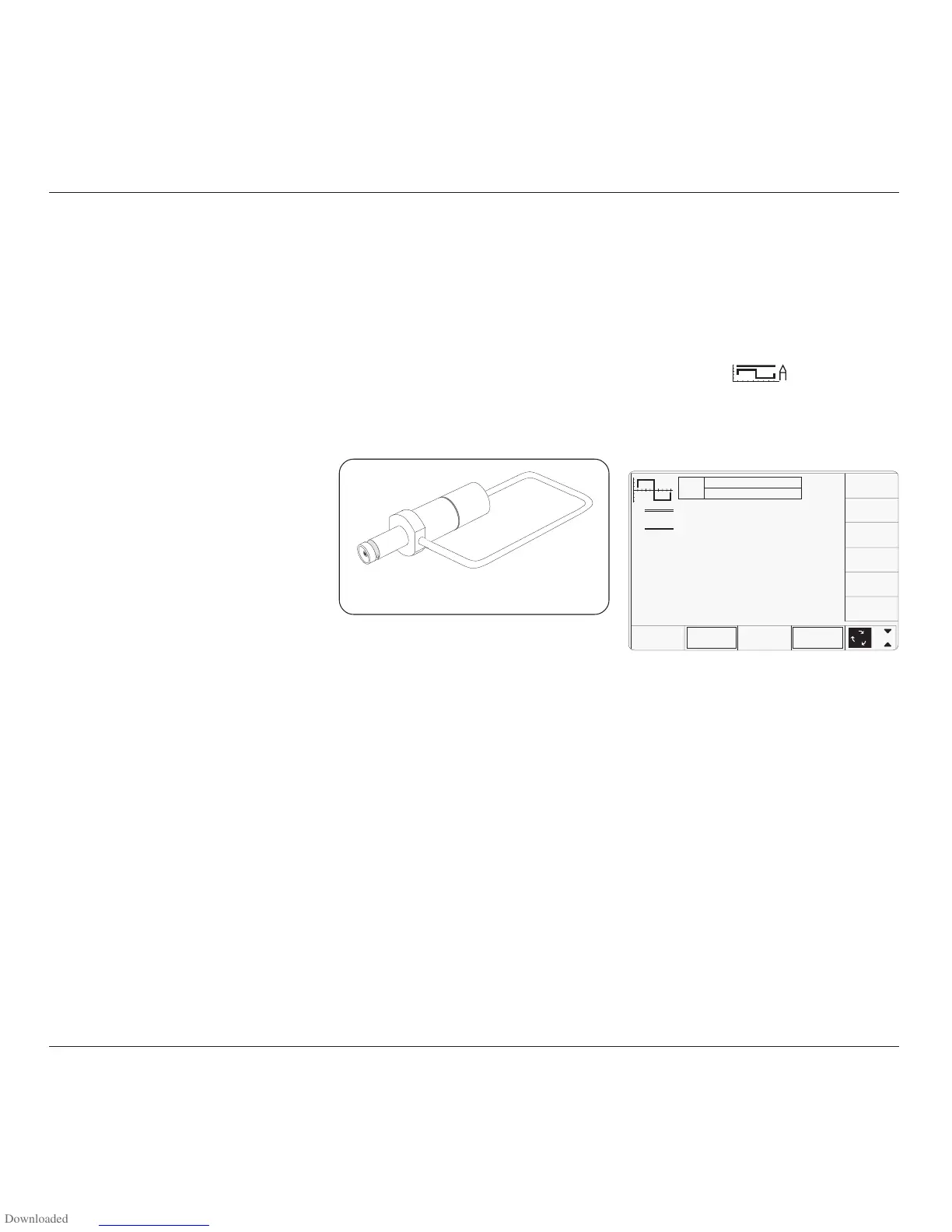
4.10.2 Current Probe
Accessory
This sub-section describes the accessory which
is used to terminate the 9500B output, and
activate UUT Oscilloscope current probe.
The accessory consists of a BNC male
connector which is plugged into the BNC
output female socket on any model head. A
loop is connected between the BNC center and
shell, which is available for insertion into the
recess of an oscilloscope current probe. The
loop presents 50Ω loading to the head:
With the 9500B 'Auxiliary' Current function
selected and output on, the output current in
the loop can be set to the UUT oscilloscope's
current probe calibration points, using 9500B
front panel controls.
Fig. 4.10.1 Current Probe Accessory