3-2 Section 3: Model 9500B Controls: Modes of Operation Descriptions assume 9500B/1100
3.2 Introduction to the Front Panel
3.2.1 Local and Remote Operation
3.2.1.1 Remote, Semi-Automatic and Manual Calibration of UUT Oscilloscopes
The 9500B has been designed to present three main user interfaces for control of UUT calibration:
• Fully-automatic operation for UUT oscilloscopes which are remotely controllable on the IEEE-488 Instrumentation Control Interface,
employing IEEE-488.2/SCPI protocols. The 9500B also includes emulation modes which minimize the software effort required for
integration into existing calibration systems designed around Tektronix CG5011 and SG5030 calibrators. Refer to Section 6.
• Semi-automatic operation using procedure memory cards to drive the 9500B, with control of the subject UUT being implemented by a form
of the UUT manufacturer's procedure through a series of user prompts. Refer to Section 5.
• Manual operation from the front panel, again with control of the subject UUT being implemented by the UUT manufacturer's procedure. Refer
to Section 4.
3.2.1.2 Use of Procedure Memory Cards
This is a form of assisted (semi-automatic) calibration, in which a memory card for a specific UUT oscilloscope is inserted into PCMCIA SLOT 1.
Running Procedure Mode will generate instructions to the operator, while setting output values on the 9500B. The sequence of these instructions
and outputs, the output specifications and the pass/fail limits conform the UUT manufacturer's calibration procedure.
3.2.1.3 Manual and Remote Calibration of the 9500B Itself
The 9500B itself must periodically be verified or calibrated against suitable traceable standards. The calibration processes for the mainframe and
Active Heads are available manually, but to gain the advantages of simplicity and throughput provided by automated procedures, these process
commands are also available via the remote interface (IEEE-488.2/SCPI protocols - Section 6.). The 9500B communicates with programmable
standards under the direction of external Control Software.
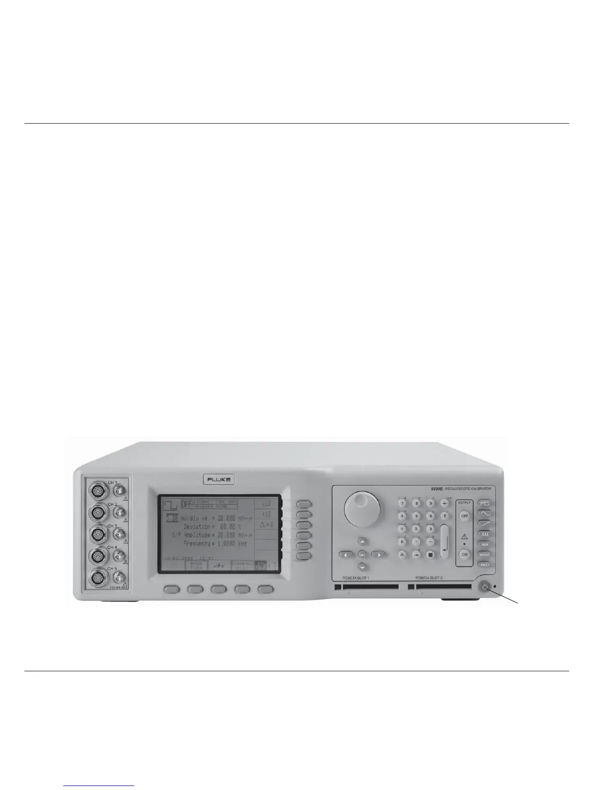
3.2.1.4 General Arrangement of Front Panel Controls
The front panel is divided into three main areas:
Center: A 'Menu' and 'Output Display' LCD screen, with grouped soft keys.
Right: A control panel, used to select and adjust operational Functions and Modes, with two slots to accept memory cards.
Left: Output Connectors, used for connection of the active heads.
These features are described in the following paragraphs.
Standby/Normal