Section 4: Using the Model 9500B — Sine Function 4.6-1
Final Width = 215mm
Descriptions assume 9500B/1100
4.6 Sine Function
This sub-section is a guide to the use of the
9500B to generate sine waves for flatness and
bandwidth calibration of oscilloscopes.
For those users who require more detailed
instructions for interconnections, and
manipulating the front panel controls, refer to
sub-sections 4.2, 4.3 and 4.4. Section 4.6 is
divided into the following sub-sections:
4.6.1 Introduction .................................................... 4.6-1
4.6.2 Default Settings .............................................. 4.6-1
4.6.3 Menu Selections ............................................. 4.6-1
4.6.3.1 Retained Channel Memory ............. 4.6-1
4.6.3.2 Right Side Screen Keys - Digit Edit/
Sequence Scroll ............................. 4.6-1
4.6.3.3 Right Side Screen Keys - Numeric
Entry............................................... 4.6-2
4.6.3.4 Bottom Screen Keys -
Digit Edit/Sequence Scroll and
Numeric Entry ................................ 4.6-2
4.6.4 Sinewave Operation ........................................ 4.6-2
4.6.4.1 Value Editing .................................. 4.6-2
4.6.4.2 Output Voltage Editing ................... 4.6-2
4.6.5 Dual Channel Operation ................................. 4.6-3
4.6.5.1 Dual Channel Selection .................. 4.6-3
4.6.6 Using the 9500B Levelled Sine Function to
Calibrate the Flatness/Bandwidth Response
of a UUT Oscilloscope .................................... 4.6-4
4.6.6.1 Introduction .................................... 4.6-4
4.6.6.2 Interconnections............................. 4.6-4
4.6.6.3 Common Setup .............................. 4.6-4
4.6.6.4 UUT Scope - Flatness Calibration
using the 9500B as a Fixed Source 4.6-4
4.6.6.5 UUT Scope - Flatness Calibration
using the 9500B as an Adjustable
Source ............................................ 4.6-4
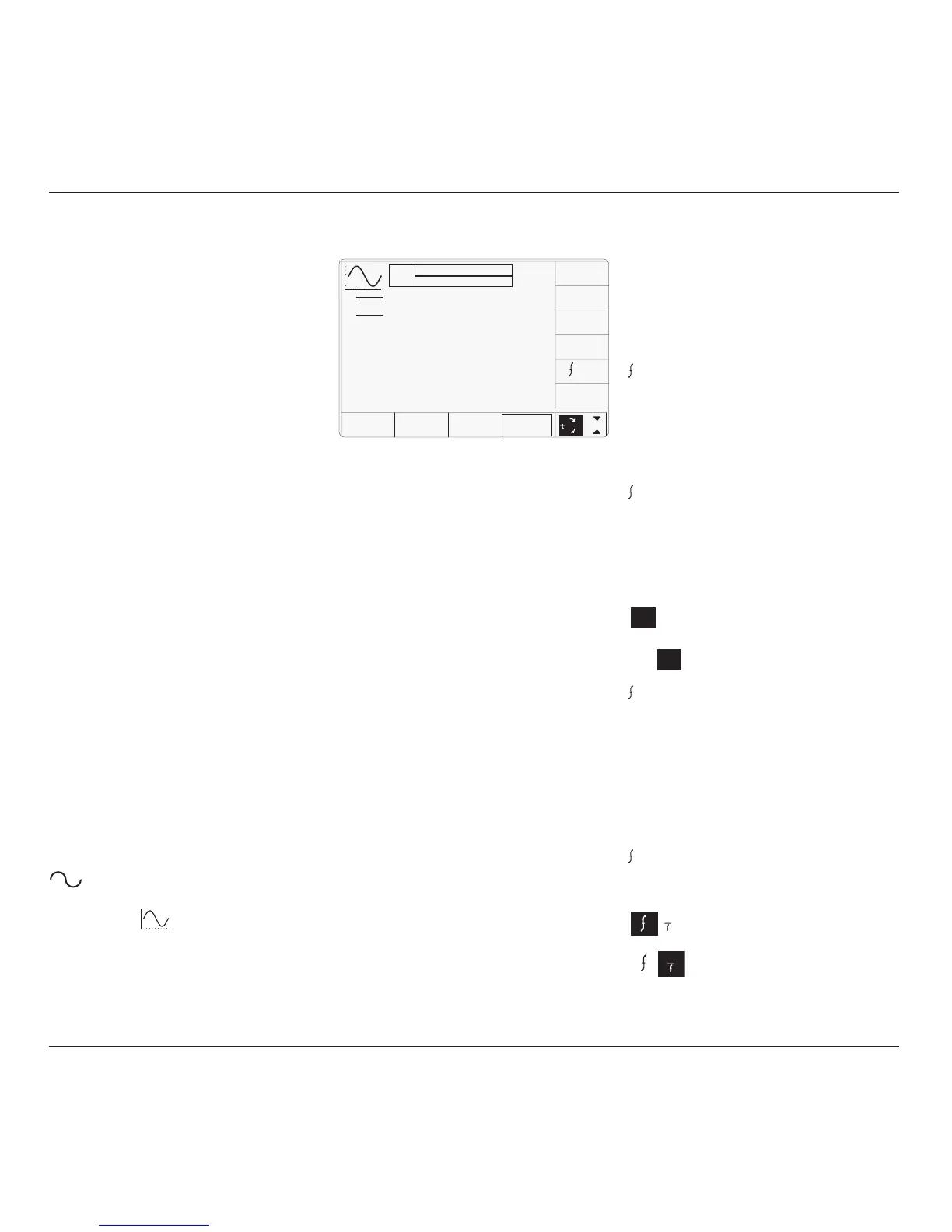
4.6.2 Default Settings
When Manual mode is selected the system
defaults into DC/Square function and shows
the DC/Square function initial menu screen.
Sine function can be accessed by pressing the
function key on the right of the
'OSCILLOSCOPE CALIBRATOR' panel.
Whenever the
menu screen is opened,
except on recovery from a standby period, it
will appear with the following default settings:
i. Cursor on Units/div:
X10 Multiplies the Units/div by ten.
÷10 Divides the Units/div by ten.
∆ = Ø Toggles the Deviation value
between the marked value and zero.
REF
Toggles between the marked
frequency and the reference
frequency.
ii. Cursor on Multiplier:
∆ = Ø Toggles the Deviation value
between the marked value and zero.
REF
Toggles between the marked
frequency and the reference
frequency.
iii. Cursor on Deviation:
∆ = Ø Toggles the Deviation value
between the marked value and zero.
Press to set Deviation value in
absolute units.
Press to set Deviation value in
percent of set value.
REF
Toggles between the marked
frequency and the reference
frequency.
iv. Cursor on Frequency/Period:
X10 Multiplies the marked value by ten.
÷10 Divides the marked value by ten.
∆ = Ø Toggles the Deviation value
between the marked value and zero.
REF
Toggles between the marked
frequency and the reference
frequency.
Press to change display from
Frequency to Period.
Press to change display from Period
to Frequency.
The above default screen has auto-selected the
frequency of 50kHz. Deviation has defaulted
to zero, and output voltage to 30.000mVp-p.
Frequency is variable between 0.1Hz and
1.1GHz (variant 9500B/1100 — for other
variants refer to specifications in Section 7).
4.6.3 Menu Selections
Except for Dual Channel operation (paras
4.6.5), all Signal Channel selection, Trigger
Channel selection, Cable selection and Trigger
Ratio operate in the same way as in DC/Square
function. Refer to paras 4.5.3.
4.6.3.1 Retained Channel Memory
Refer to para 4.5.3.6.
4.6.3.2 Right Side Screen Keys —
Digit Edit/Sequence Scroll
Keys operate on the value marked by the
cursor. The key labels will change depending
on the cursor position, as indicated in the next
column:
∆% ∆V
∆% ∆V
1
1
4.6.1 Introduction
TODAY'S DATE TIME
OFF
SIGNAL CH1 5ØΩ
TRIGGER NONE
x 1Ø
÷ 1Ø
∆ = Ø
5.ØØ mV/div x6 = 3Ø.ØØØ mV
pk-pk
Deviation
= ØØ.ØØ %
O/P
Amplitude
= 3Ø.ØØØ mV
pk-pk
Frequency
= 5Ø.ØØØ kHz
CHANNEL
SELECT
1
2
5
1.Ø
REF