Section 4: Using the Model 9500B — Composite Video Function 4.11-1
Final Width = 215mm
Descriptions assume 9500B/1100
When Manual mode is selected the system
defaults into DC/Square function and shows
the DC/Square function initial menu screen.
The Composite Video function is accessed by
first pressing the 'Aux' key on the right of the
'OSCILLOSCOPE CALIBRATOR' panel,
then pressing the
soft key on the right
of the screen.
Whenever the
menu screen is opened,
except on recovery from a standby period, it
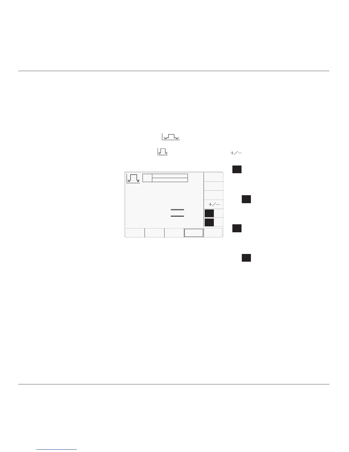
will appear with the following default settings:
4.11.3 Default Settings
625
50Hz
525
60Hz
625
50Hz
525
60Hz
4.11 Composite Video Function
This sub-section is a guide to the use of the
9500B to generate composite video for video
trigger sensitivity calibration of oscilloscopes.
For those users who require more detailed
instructions for interconnections, and
manipulating the front panel controls, refer to
sub-sections 4.2, 4.3 and 4.4. Section 4.11 is
divided into the following sub-sections:
4.11.1 Introduction .................................................. 4.11-1
4.11.2 Signals and Triggers .................................... 4.11-1
4.11.3 Default Settings ............................................ 4.11-1
4.11.4 Menu Selections ........................................... 4.11-1
4.11.4.1 Retained Channel Memory ........... 4.11-1
4.11.4.2 Right Side Screen Keys ................ 4.11-1
4.11.4.3 Bottom Screen Keys ..................... 4.11-1
4.11.5 Composite Video Function Operation ........... 4.11-2
4.11.5.1 Value Editing ................................ 4.11-2
4.11.6 Using the 9500B Composite Video Function to
Calibrate Video Trigger Sensitivity of a UUT
Oscilloscope ................................................. 4.11-2
4.11.6.1 Introduction .................................. 4.11-2
4.11.6.2 Interconnections ........................... 4.11-2
4.11.6.3 Calibration Procedure .................. 4.11-2
4.11.2 Signals and Triggers
The composite video signal generated by the
9500B is standard 625 line or 525 line video
with both frame and composite synch pulses,
and an inverted version of the composite
waveform is available. As shown by the screen
icon, three luminance levels are available.
The 9500B trigger channel can output either
composite or frame synchronizing pulses,
without the video. All variants can be selected
from the front panel.
4.11.1 Introduction
TODAY'S DATE TIME
OFF
SIGNAL CH1 5ØΩ
TRIGGER NONE
O/P
Amplitude
= 1.ØØ V
pk-pk
CHANNEL
SELECT
625
50Hz
525
60Hz
TRIG
COMP
TRIG
FRAME
The above default screen has auto-selected
625 lines / 50Hz and triggers will be from
composite video. Amplitude has defaulted to
a luminance level of 'White' at 1.0V p-p.
4.11.4 Menu Selections
Signal Channel selection, Trigger Channel
selection and Cable selection all operate in the
same way as in DC/Square function. Trigger
Ratio is not available in Composite Video
function. Refer to paras 4.5.3.
Note: Without Option 5, only one signal
channel and one trigger channel is
available.
4.11.4.1 Retained Channel Memory
Refer to para 4.5.3.6.
4.11.4.2 Right Side Screen Keys
The cursor is available only on the Luminance
Level parameter (Scope mode). Three
luminance levels are defined (para 4.11.5.1).
The key labels will change depending on other
key selections:
Default Screen:
Toggles between upright and
inverted composite video.
Currently 50Hz line supply with
625 raster lines. Press to select for
60Hz line supply with 525 raster
lines.
Currently 60Hz line supply with
525 raster lines. Press to select for
50Hz line supply with 625 raster
lines.
Currently Composite synch pulses
on the Trigger channel. Press to
output Frame synch pulses on the
Trigger channel.
Currently Frame synch pulses on
the Trigger channel. Press to output
Composite synch pulses on the
Trigger channel.
4.11.4.3 Bottom Screen Keys
CHANNEL Permits the screen signal setup to
SELECT be routed to any of the five heads,
allowing selection of trigger
channel and cable channel (paras
4.5.3).
TRIG
COMP
TRIG
FRAME
TRIG
COMP
TRIG
FRAME
Luminance Level = White