Section 4: Using the Model 9500B — Input Leakage Function 4.17-1
Final Width = 215mm
Descriptions assume 9500B/1100
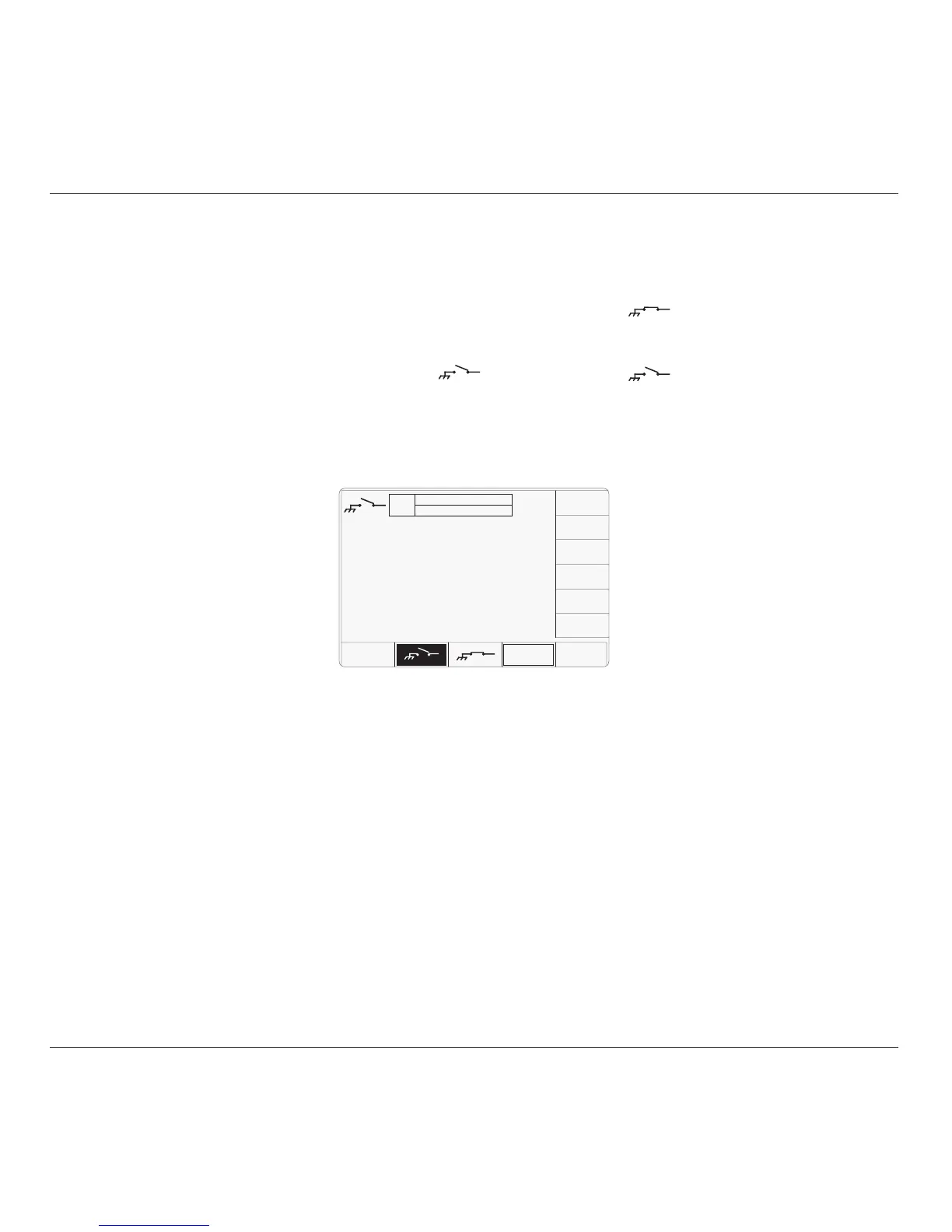
The above default screen has auto-selected the
open-circuit output, as indicated by the icon in
the top left corner, and the highlighted screen
key on the bottom row.
4.17.4 Menu Selections
Signal Channel selection, Trigger Channel
selection and Cable selection all operate in the
same way as in DC/Square function. Refer to
paras 4.5.3.
4.17.4.1 Retained Channel Memory
Refer to para 4.5.3.6.
4.17.3 Default Settings
When Manual mode is selected the system
defaults into DC/Square function and shows
the DC/Square function initial menu screen.
The Input Leakage function is accessed by first
pressing the 'Aux' key on the right of the
'OSCILLOSCOPE CALIBRATOR' panel,
then pressing the
soft key on the bottom
of the screen.
Whenever the Input Leakage menu screen is
opened, except on recovery from a standby
period, it will appear with the following default
settings:
4.17 Input Leakage Function
This sub-section is a guide to using the 9500B
to short-circuit and open-circuit channel inputs
of a UUT oscilloscope to test for input leakage.
For those users who require more detailed
instructions for interconnections, and
manipulating the front panel controls, refer to
sub-sections 4.2, 4.3 and 4.4.
Section 4.17 is divided into the following sub-
sections:
4.17.1 Introduction .................................................. 4.17-1
4.17.2 Input Leakage Test ........................................ 4.17-1
4.17.3 Default Settings ............................................ 4.17-1
4.17.4 Menu Selections ........................................... 4.17-1
4.17.4.1 Retained Channel Memory ........... 4.17-1
4.17.5 Input Leakage Operation ............................... 4.17-1
4.17.5.1 Bottom Screen Keys ..................... 4.17-1
4.17.5.2 Open Circuit Output Leakage
Specification ................................ 4.17-1
4.17.6 Using the 9500B to Test the Input Leakage Current
of a UUT Oscilloscope .................................. 4.17-2
4.17.6.1 Introduction .................................. 4.17-2
4.17.6.2 Interconnections ........................... 4.17-2
4.17.6.3 9500B and UUT Scope Setup ....... 4.17-2
4.17.6.4 Sequence of Operations ............... 4.17-2
4.17.2 Input Leakage Test
UUT Oscilloscope input leakage current can
be tested by noting the difference in deflection
when a channel's input is open-circuited and
when it is short-circuited.
With the 9500B 'Auxiliary' Input Leakage
function selected, open and short circuits can
be imposed on the selected channel input,
using 9500B front panel controls.
Scope triggers at 100Hz are provided if
required.
4.17.1 Introduction
4.17.5 Input Leakage Operation
4.17.5.1 Bottom Screen Keys
Press to select short-circuit output,
and provide a one-shot trigger to
the UUT.
Press to select open-circuit output,
and provide a one-shot trigger to
the UUT.
CHANNEL Permits the screen signal setup to
SELECT be routed to any of the five heads,
allowing selection of trigger
channel and cable channel (paras
4.5.3).
AUTO Produces a train of triggers at 100Hz
TRIG to trigger the UUT oscilloscope.
4.17.5.2 Open Circuit Output
Leakage Specification
Output Leakage Current
The 9500B output leakage current in any
channel output is less than ±50pA.
TODAY'S DATE TIME
OFF
SIGNAL CH1 1MΩ
TRIGGER NONE
UUT Input Leakage Test
CHANNEL
SELECT
AUTO
TRIG