Section 4: Using the Model 9500B — Edge Function 4.7-1
Final Width = 215mm
Descriptions assume 9500B/1100
4.7 Edge Function
This sub-section is a guide to the use of the
9500B for generating defined pulse edges to
examine oscilloscope pulse response.
For those users who require more detailed
instructions for interconnections, and
manipulating the front panel controls, refer to
sub-sections 4.2, 4.3 and 4.4.
4.7.1 Introduction .................................................... 4.7-1
4.7.2 Default Settings .............................................. 4.7-1
4.7.3 Menu Selections ............................................. 4.7-1
4.7.3.1 Retained Channel Memory ............. 4.7-1
4.7.3.2 Right Side Screen Keys - Digit Edit 4.7-1
4.7.3.3 Right Side Screen Keys - Direct Edit 4.7-2
4.7.3.4 Bottom Screen Keys -
Digit and Direct Edit ....................... 4.7-2
4.7.4 Edge Function Operation ................................ 4.7-2
4.7.4.1 Value Editing .................................. 4.7-2
4.7.4.2 Output Voltage Editing ................... 4.7-2
4.7.4.3 Low Voltage (LV) and
High Voltage (HV) States ............... 4.7-3
4.7.5 Using Active Head Models 9510, 9520, 9530 4.7-3
4.7.5.1 Introduction .................................... 4.7-3
4.7.6 Using the 9500B Edge Function to Calibrate the
Pulse Response of a UUT Oscilloscope .......... 4.7-4
4.7.6.1 Introduction .................................... 4.7-4
4.7.6.2 Interconnections............................. 4.7-4
4.7.6.3 Common Setup .............................. 4.7-4
4.7.6.4 UUT Scope - Pulse Response
Calibration using the 9500B
as a Fixed Source ........................... 4.7-4
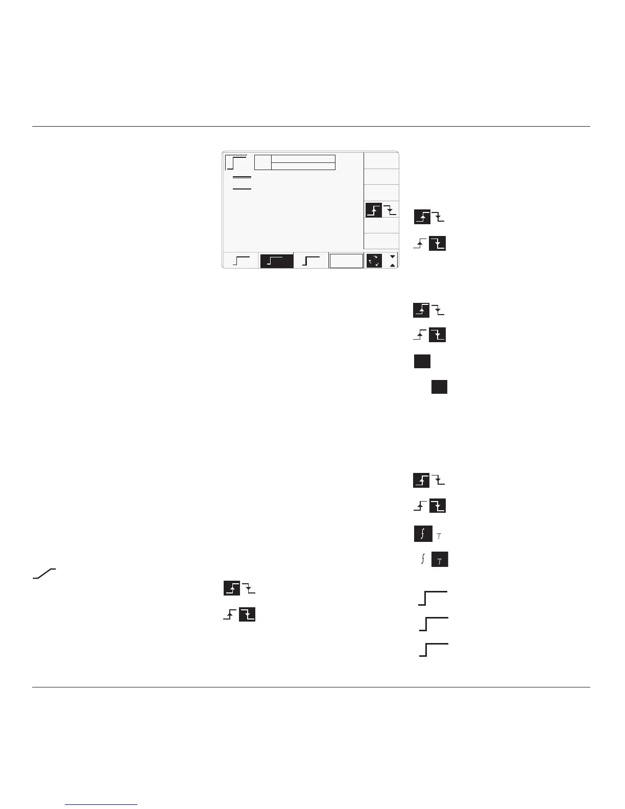
4.7.2 Default Settings
When Manual mode is selected the system
defaults into DC/Square function and shows
the DC/Square function initial menu screen.
Edge function can be accessed by pressing the
function key on the right of the
'OSCILLOSCOPE CALIBRATOR' panel.
Whenever the Edge menu screen is opened,
except on recovery from a standby period, it
will appear with the following default settings:
ii. Cursor on Multiplier:
∆ = Ø Toggles the Deviation value
between the marked value and zero.
Press to select falling edge
(Function icon follows).
Press to select rising edge
(Function icon follows).
iii. Cursor on Deviation:
∆ = Ø Toggles the Deviation value
between the marked value and zero.
Press to select falling edge
(Function icon follows).
Press to select rising edge
(Function icon follows).
Press to set Deviation value in
absolute units.
Press to set Deviation value in
percent of set value.
iv. Cursor on Frequency/Period:
X10 Multiplies the marked value by ten.
÷10 Divides the marked value by ten.
∆ = Ø Toggles the Deviation value
between the marked value and zero.
Press to select falling edge
(Function icon follows).
Press to select rising edge
(Function icon follows).
Press to change display from
Frequency to Period.
Press to change display from Period
to Frequency.
v. Cursor on Fast:
Press to select 150ps pulse function.
(Function icon follows).
Press to select 70ps pulse function.
(Function icon follows).
Press to select 25ps pulse function.
(Function icon follows).
The above default screen has auto-selected a
frequency of 1MHz, a rise time of 500ps, zero
deviation and an output level of 1Vpk-pk.
4.7.3 Menu Selections
Signal Channel selection, Trigger Channel
selection, Cable selection and Trigger Ratio all
operate in the same way as in DC/Square
function. Refer to paras 4.5.3.
4.7.3.1 Retained Channel Memory
Refer to para 4.5.3.6.
4.7.3.2 Right Side Screen Keys —
Digit Edit
Keys operate on the value marked by the
cursor. The key labels will change depending
on the cursor position, as indicated.:
i. Cursor on Units/div:
X10 Multiplies the Units/div by ten.
÷10 Divides the Units/div by ten.
∆ = Ø Toggles the Deviation value
between the marked value and zero.
Press to select falling edge
(Function icon follows).
Press to select rising edge
(Function icon follows).
∆% ∆V
∆% ∆V
1
1
4.7.1 Introduction
continued overleaf
→
TODAY'S DATE TIME
500ps
OFF
SIGNAL CH1 5ØΩ
TRIGGER NONE
x 1Ø
÷ 1Ø
∆ = Ø
Ø.2Ø V /div x5 = 1.ØØØØ V
pk-pk
Deviation
= ØØ.ØØ %
O/P
Amplitude
= 1.ØØØØ V
pk-pk
Frequency
= 1.ØØØØ MHz
Rise Time
= ------
CHANNEL
SELECT
1
2
5
1.Ø
HV
500ps
FAST
150ps
70ps
25ps