Section 4: Using the Model 9500B — Time Markers Function 4.8-1
Final Width = 215mm
Descriptions assume 9500B/1100
4.8 Time Markers Function
4.8.2 Default Settings
When Manual mode is selected the system
defaults into DC/Square function and shows
the DC/Square function initial menu screen.
Time Markers function can be accessed by
pressing the
function key on the right of
the 'OSCILLOSCOPE CALIBRATOR' panel.
Whenever the
menu screen is opened,
except on recovery from a standby period, it
will appear with the following default settings,
although some settings may have been made
non-volatile (refer to para 4.5.3.6):
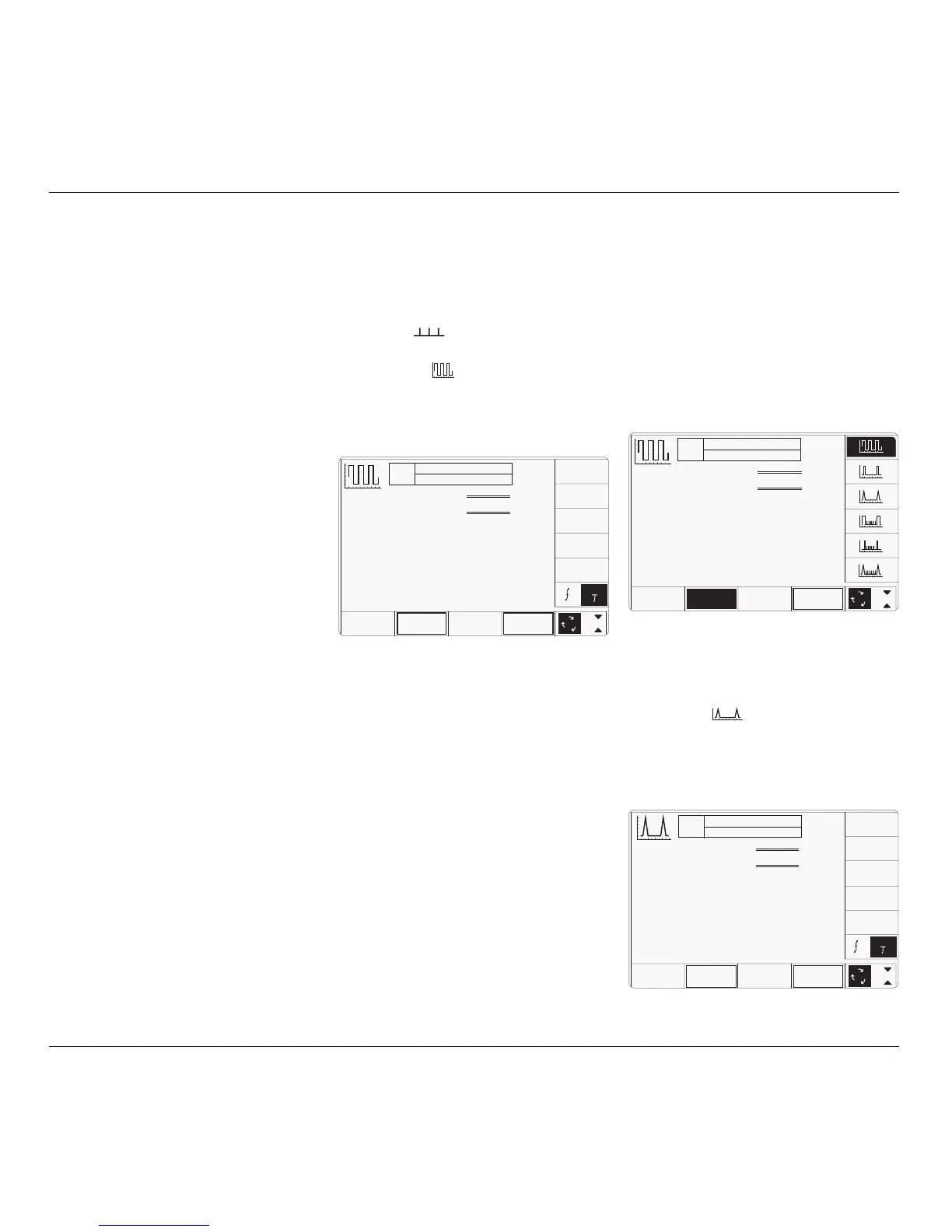
The above default screen has auto-selected the
square waveform, as indicated by the icon in
the top left corner. Square waveform Period is
variable between 10ns and 50s (sine waveform
is used above approx. 100MHz). Sine
waveform Period is variable between 500ps
and 10ns (variant 9500B/1100 — for other
variants refer to specifications in Section 7).
Period has defaulted to 1µs (square), deviation
'∆' to zero, and output voltage to 1.0000Vp-p.
The Duty Cycle is fixed at a nominal 50%.
4.8.3 Menu Selections
Signal Channel selection, Trigger Channel
selection, Cable selection and Trigger Ratio all
operate in the same way as in DC/Square
function. Refer to paras 4.5.3.
The WAVEFORM key label is highlighted to
indicate that waveform selection is available,
as is the presently-selected waveform icon.
Pressing one of the waveform keys (for
example: the
key) to select a different
waveform will return to the previous screen
(providing that the frequency is appropriate),
with the icon of the selected waveform showing
in the top left corner:
4.8.3.1 Retained Channel Memory
Refer to para 4.5.3.6.
4.8.3.2 Choosing a Waveshape
All waveshapes (Marker Styles) in this function
can be selected on a second menu screen. This
is activated by pressing the '
WAVEFORM'
screen key on the bottom row. The screen
changes to show the available waveforms:
TODAY'S DATE TIME
OFF
SIGNAL CH1 5ØΩ
TRIGGER NONE
x 1Ø
÷ 1Ø
∆ = Ø
1
2
5
1.Ø
WAVE
FORM
CHANNEL
SELECT
Time Marker = 1.ØØØØ µs
Deviation
= ØØ.ØØ %
Period = 1.ØØØØ µs
O/P
Amplitude
= 1.ØØØØ V
pk-pk
LINE
FREQ
4.8.1 Introduction
This sub-section is a guide to the use of the
9500B for generating square waves and DC
voltages for use for amplitude calibration of
oscilloscopes.
For those users who require more detailed
instructions for interconnections, and
manipulating the front panel controls, refer to
sub-sections 4.2, 4.3 and 4.4. Section 4.8 is
divided into the following sub-sections:
4.8.1 Introduction .................................................... 4.8-1
4.8.2 Default Settings .............................................. 4.8-1
4.8.3 Menu Selections ............................................. 4.8-1
4.8.3.1 Retained Channel Memory ............. 4.8-1
4.8.3.2 Choosing a Waveshape .................. 4.8-1
4.8.3.3 Right Side Screen Keys - Digit Edit 4.8-2
4.8.3.4 Right Side Screen Keys - Direct Edit 4.8-2
4.8.3.5 Bottom Screen Keys -
Digit and Direct Edit ....................... 4.8-2
4.8.4 Time Markers Operation ................................. 4.8-2
4.8.4.1 Value Editing .................................. 4.8-2
4.8.4.2 Output Period Editing ..................... 4.8-3
4.8.4.3 Highlighted Marker Styles .............. 4.8-3
4.8.5 Using the 9500B Time Markers Function to
Calibrate the Time Base of a UUT
Oscilloscope ................................................... 4.8-4
4.8.5.1 Introduction .................................... 4.8-4
4.8.5.2 Interconnections............................. 4.8-4
4.8.5.3 Common Setup .............................. 4.8-4
4.8.5.4 UUT Scope - Time Base Calibration
using the 9500B as a Fixed Source 4.8-4
4.8.5.5 UUT Scope - Time Base Calibration
using the 9500B as an Adjustable
Source ............................................ 4.8-4
TODAY'S DATE TIME
OFF
SIGNAL CH1 5ØΩ
TRIGGER NONE
x 1Ø
÷ 1Ø
∆ = Ø
Time Marker = 1.ØØØØ µs
Deviation
= ØØ.ØØ %
Period = 1.ØØØØ µs
O/P
Amplitude
= 1.ØØØØ V
pk-pk
WAVE
FORM
CHANNEL
SELECT
1.Ø
LINE
FREQ
1
1
1
2
5
TODAY'S DATE TIME
OFF
SIGNAL CH1 5ØΩ
TRIGGER NONE
WAVE
FORM
1
2
5
1.Ø
CHANNEL
SELECT
Time Marker = 1.ØØØØ µs
Deviation
= ØØ.ØØ %
Period = 1.ØØØØ µs
O/P
Amplitude
= 1.ØØØØ V
pk-pk