Section 4: Using the Model 9500B — Zero Skew Function 4.14-1
Final Width = 215mm
Descriptions assume 9500B/1100
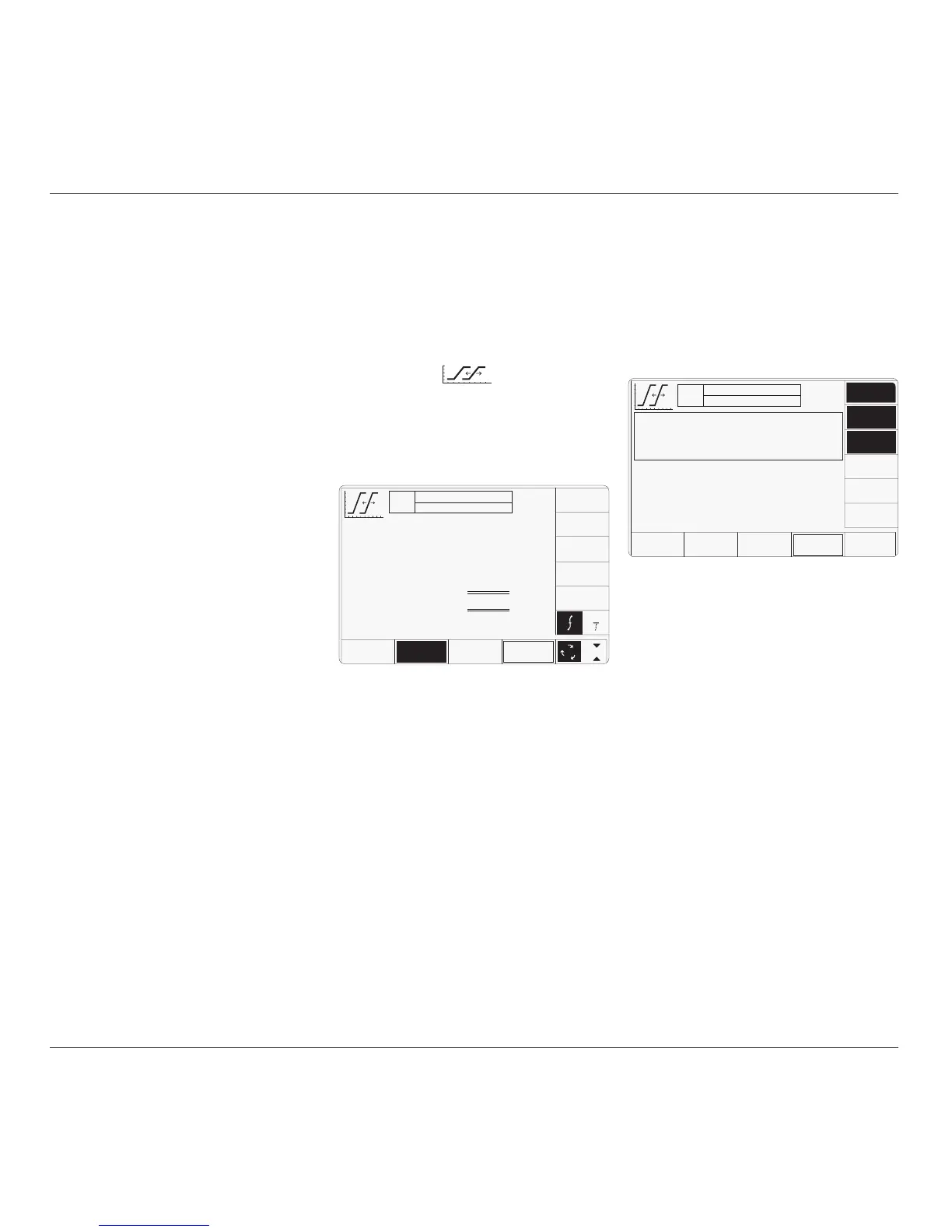
The above default screen has auto-selected
'Default Alignment', as indicated by the top
line of text and the highlighted screen key on
the bottom row. The unequallized (default)
alignment has a maximum skew of ±50ps
between channels. The amplitude and default
frequency are also shown on the screen.
The selected output channels are listed in the
central box at the top of the screen.
4.14.3 Menu Selections
4.14.3.1 Signal Channel Selection
Signal Channel selection differs from other
functions in that all channels fitted with an
active head will be selected on entering the
function. In the unit used for this description,
channels 1, 2 and 3 had heads attached, nothing
was fitted to channel 4, and a trigger cable was
fitted to channel 5.
4.14 Zero Skew Function
'Skew' is defined as the relative delay between
two or more selected channels. If the channel
delays are equallized, then the condition is
known as 'Zero Skew'. This sub-section is a
guide to using the 9500B Zero Skew function
to:
a. Adjust selected 9500B channels to
equallize their delays.
b. Use the same channels as sources for
measuring the skew between input channels
of a UUT oscilloscope.
c. Also, two cable channels can be precision-
aligned.
For those users who require more detailed
instructions for interconnections, and
manipulating the front panel controls, refer to
sub-sections 4.2, 4.3 and 4.4.
Section 4.14 is divided into the following sub-
sections:
4.14.1 Introduction .................................................. 4.14-1
4.14.2 Default Settings ............................................ 4.14-1
4.14.3 Menu Selections ........................................... 4.14-1
4.14.3.1 Signal Channel Selection ............. 4.14-1
4.14.3.2 Right Side Screen Keys —
Digit Edit/Sequence Scroll ........... 4.14-2
4.14.3.3 Right Side Screen Keys —
Numeric Entry .............................. 4.14-2
4.14.3.4 Bottom Screen Keys ..................... 4.14-2
4.14.4 Zero Skew Operation .................................... 4.14-2
4.14.4.1 Precision Alignment of
9500B Channel Outputs ............... 4.14-2
4.14.4.2 Preservation of Alignment ............ 4.14-2
4.14.5 Measurement of UUT Oscilloscope
Channel Skew ............................................... 4.14-3
4.14.5.1 Introduction .................................. 4.14-3
4.14.5.2 Interconnections ........................... 4.14-3
4.14.5.3 9500B and UUT Scope Setup ....... 4.14-3
4.14.5.4 Sequence of Operations ............... 4.14-3
4.14.1 Introduction
Neither channel 4 nor 5 has an active head
fitted. The highlights on channels 1, 2 and 3
indicate that only these channels have heads
active (confirmed by the legend in the top
central box), and for these zero skew can be
used. Toggling any one of these soft keys
deselects and reselects that channel. Note that
the function cannot operate with only one
channel selected, which will cause an error
message to appear on the screen.
In Zero Skew function, expected load is fixed
at 50Ω on all signal channels, so the 50Ω/1MΩ
switching soft key is absent.
In this function, the 'trigger channel' soft key is
absent.
When the Channel Select screen is presented,
adjustment of Frequency/Period is inhibited.
Pressing the '
EXIT' key will revert back to the
standard Zero Skew screen of para 4.14.2, the
top central box showing the channels which
have been selected.
When Manual mode is selected the system
defaults into DC/Square function and shows
the DC/Square function initial menu screen.
The Zero Skew function is accessed by first
pressing the 'Aux' key on the right of the
'OSCILLOSCOPE CALIBRATOR' panel,
then pressing the soft key on the right
of the screen.
Whenever the Zero Skew menu screen is
opened, except on recovery from a standby
period, it will appear with the following default
settings:
The required channels can be selected on a
second menu screen. This is activated by
pressing the 'CHANNEL SELECT' screen key
on the bottom row. The screen changes to
show the available channels, which are already
selected:
4.14.2 Default Settings
continued overleaf
→
TODAY'S DATE TIME
OFF
ACTIVE CHANNELS
CHS 1, 2, 3, 50Ω
CHANNEL
SELECT
x 1Ø
÷ 1Ø
Default Alignment
Skew
≤±50 ps
O/P
Amplitude
= 1.ØØØØ V
pk-pk
Frequency
= 1.ØØØØ kHz
1
2
5
1.Ø
DEFAULT
ALIGN
ADJUST
ALIGN
1
TODAY'S DATE TIME
OFF
ACTIVE CHANNELS
CHS 1,
2, 3, 50Ω
O/P
Amplitude
= 1.ØØØØ V
pk-pk
Frequency
= 1.ØØØØ kHz
CHANNEL 1
>
Standard Head
CHANNEL 2
>
Standard Head
CHANNEL 3
>
Standard Head
CHANNEL 4
>
No Head
CHANNEL 5
>
Trigger Cable
SIGNAL
CH 4
SIGNAL
CH 5
SIGNAL
CH 1
EXIT
SIGNAL
CH 2
SIGNAL
CH 3
CABLE
SELECT