Section 4: Using the Model 9500B — DC/Square Function 4.5-1
Final Width = 215mm
Descriptions assume 9500B/1100
4.5 DC/Square Function
4.5.1 Introduction
This sub-section is a guide to the use of the
9500B for generating square waves and DC
voltages for use for amplitude calibration of
oscilloscopes.
For those users who require more detailed
instructions for interconnections, and
manipulating the front panel controls, refer to
sub-sections 4.2, 4.3 and 4.4. Section 4.5 is
divided into the following sub-sections:
4.5.1 Introduction .................................................... 4.5-1
4.5.2 Default Settings .............................................. 4.5-1
4.5.3 Menu Selections ............................................. 4.5-1
4.5.3.1 Signal Channels ............................. 4.5-1
4.5.3.2 UUT Triggers.................................. 4.5-2
4.5.3.3 Trigger Channel Selection .............. 4.5-2
4.5.3.4 Cable Selection .............................. 4.5-2
4.5.3.5 Trigger Ratio .................................. 4.5-3
4.5.3.6 Retained Channel Memory ............. 4.5-3
4.5.3.7 Choosing a Waveshape .................. 4.5-3
4.5.3.8 DC Selection .................................. 4.5-3
4.5.3.9 DC/Square Selection Summary ...... 4.5-3
4.5.4 DC/Square Operation ..................................... 4.5-4
4.5.4.1 Right Side Screen Keys - Digit Edit/
Sequence Scroll ............................. 4.5-4
4.5.4.2 Right Side Screen Keys -
Numeric Entry ................................ 4.5-4
4.5.4.3 Bottom Screen Keys - Digit Edit,
Sequence Scroll and Numeric Entry 4.5-4
4.5.5 Square Operation ............................................ 4.5-4
4.5.5.1 Value Editing .................................. 4.5-4
4.5.5.2 Output Voltage Editing ................... 4.5-5
4.5.5.3 Low Voltage (LV) and
High Voltage (HV) States ............... 4.5-5
4.5.6 Using the 9500B Square Function to Calibrate the
Amplitude Response of a UUT Oscilloscope ... 4.5-6
4.5.6.1 Introduction .................................... 4.5-6
4.5.6.2 Interconnections............................. 4.5-6
4.5.6.3 UUT Scope - Amplitude Calibration
using the 9500B as a Fixed Source 4.5-6
4.5.6.4 UUT Scope - Amplitude Calibration
using the 9500B as an Adjustable
Source ............................................ 4.5-7
4.5.7 DC Operation .................................................. 4.5-8
4.5.7.1 Polarity ........................................... 4.5-8
4.5.7.2 Value Editing .................................. 4.5-8
4.5.7.3 Output Voltage Editing ................... 4.5-8
4.5.7.4 Low Voltage (LV) and
High Voltage (HV) States ............... 4.5-8
4.5.7.5 Multi Channel DC Operation .......... 4.5-8
4.5.8 Using the 9500B DC Function to Calibrate the
Amplitude Response of a UUT Oscilloscope ... 4.5-9
4.5.8.1 Introduction .................................... 4.5-9
4.5.8.2 Interconnections............................. 4.5-9
4.5.8.3 UUT Scope — Amplitude Calibration
using the 9500B as a Fixed Source of
DC Voltage ..................................... 4.5-9
4.5.8.4 UUT Scope — Amplitude Calibration
using the 9500B as an Adjustable
Source of DC Voltage ................... 4.5-10
TODAY'S DATE TIME
OFF
SIGNAL CH1 5ØΩ
TRIGGER NONE
O/P
Amplitude
= 2Ø.ØØØ mV
pk-pk
Frequency
= 1.ØØØØ kHz
SIGNAL
CH 2
CHANNEL 1
>
9530 1.1Ghz 150ps
CHANNEL 2
>
9530 1.1GHz 150ps
CHANNEL 3
>
9510 1.1GHz 500ps
CHANNEL 4
>
No Head
CHANNEL 5
>
No Head
SIGNAL
CH 3
SIGNAL
CH 4
SIGNAL
CH 5
SIGNAL
CH 1
EXIT
TRIGGER
CHANNEL
LOAD
5ØΩ 1MΩ
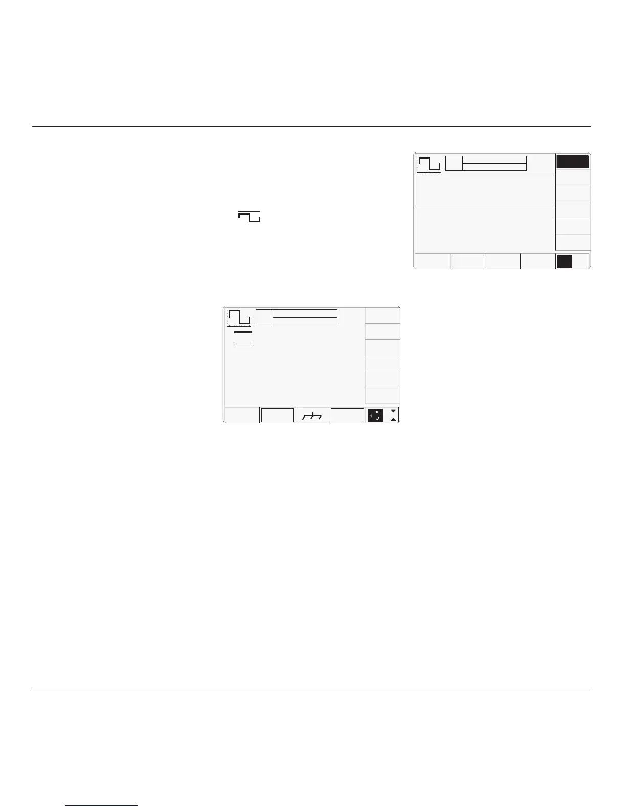
4.5.2 Default Settings
When Manual mode is selected the system
defaults into DC/Square function and shows
the DC/Square function initial menu screen.
Otherwise, the function is accessed by pressing
the
function key at the top right of the
'OSCILLOSCOPE CALIBRATOR' panel.
Whenever the DC/Square menu screen is
opened, except on recovery from a standby
period, it may appear with the following default
settings, although some settings may have
been made non-volatile (refer to para 4.5.3.6):
The above default screen has auto-selected the
positive square waveform, as indicated by the
icon in the top left corner. Frequency is variable
between 10.000Hz and 100.00kHz. Frequency
has defaulted to 1kHz, deviation '∆' to zero,
and output voltage to 20.000mVp-p. The Duty
Cycle is fixed at a nominal 50%.
4.5.3 Menu Selections
4.5.3.1 Signal Channels
Each channel leads to specified pair of active
head connectors, and a head (if fitted). The
required channel can be selected on a second
menu screen. This is activated by pressing the
'CHANNEL SELECT' screen key on the bottom
row. The screen changes to show the available
channels (the presence of a head is detected
when fitted):
TODAY'S DATE TIME
OFF
SIGNAL CH1 5ØΩ
TRIGGER NONE
x 1Ø
÷ 1Ø
∆ = Ø
5.ØØ mV/div x4 = 2Ø.ØØØ mV
pk-pk
Deviation
= ØØ.ØØ %
O/P
Amplitude
= 2Ø.ØØØ mV
pk-pk
Frequency
= 1.ØØØØ kHz
WAVE
FORM
CHANNEL
SELECT
1
2
5
1.Ø
As can be seen from the screen, Model 9530
heads are fitted to channels 1 and 2, a Model
9510 head is fitted to channel 3, and no heads
are fitted to channels 4 and 5.
The highlight on channel 1 indicates that this
channel is selected for signal output, (confirmed
by the legend in the top central box). Pressing
any one of the right side soft keys selects that
channel for the signal output.
Expected load is confirmed as 50Ω (once
selected, the selection applies to all signal
channels). The right-most key on the bottom
row toggles between expected loads of 50Ω
and 1MΩ. The presence of '
TRIGGER NONE'
in the top central box indicates that no trigger
channel has been nominated.
Pressing the '
EXIT' key will revert back to the
standard DC/Square screen of para 4.5.2.
Note:
When a channel's head is finally connected to
the UUT oscilloscope, and the 9500B output is
turned on, the 9500B will measure the UUT
load. If the measured load is outside the
specification for the expected load, then an
error message will appear on the screen:
'Load Mismatch Detected UUT >150Ω'
for 50Ω selected;
'Load Mismatch Detected UUT <50kΩ'
for 1MΩ selected.
continued overleaf
→