Section 2: Installing the Model 9500B 2-7
Pin Designations
112
1324
2.8
Connectors and Pin Designations
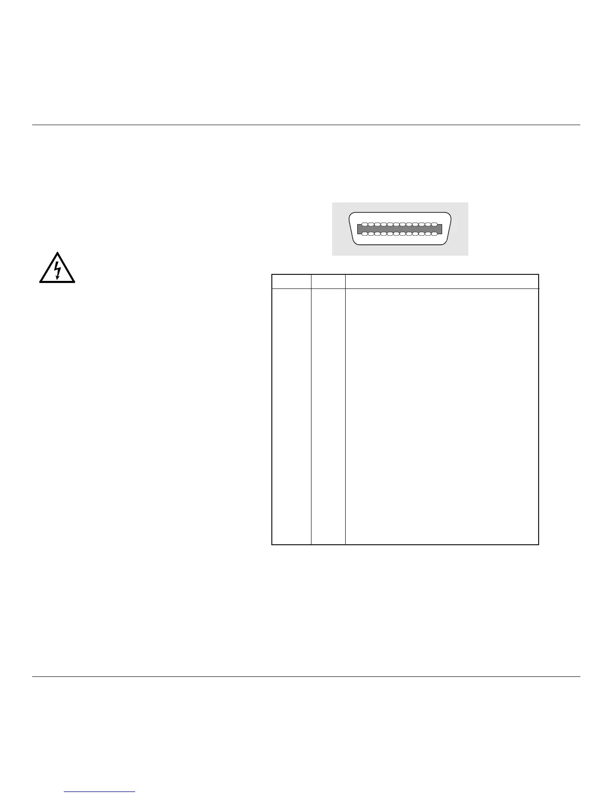
2.8.1 IEEE-488 Input/Output (Rear Panel)
This 24-way input/output connector on the rear panel, which is labelled IEEE-488, is
directly compatible with the IEEE-488 and IEC-625 Interface Bus standards.
Pin Layout
Pin No. Name Description
1 DIO 1 Data Input Output Line 1
2 DIO 2 Data Input Output Line 2
3 DIO 3 Data Input Output Line 3
4 DIO 4 Data Input Output Line 4
5 EOI End or Identify
6 DAV Data Valid
7 NRFD Not ready for Data
8 NDAC Not Data Accepted
9 IFC Interface Clear
10 SRQ Service Request
11 ATN Attention
12 SHIELD Screening on cable (connected to Safety Ground)
13 DIO 5 Data Input Output Line 5
14 DIO 6 Data Input Output Line 6
15 DIO 7 Data Input Output Line 7
16 DIO 8 Data Input Output Line 8
17 REN Remote Enable
18 GND 6 Ground wire of twisted pair with DAV
19 GND 7 Ground wire of twisted pair with NRFD
20 GND 8 Ground wire of twisted pair with NDAC
21 GND 9 Ground wire of twisted pair with IFC
22 GND 10 Ground wire of twisted pair with SRQ
23 GND 11 Ground wire of twisted pair with ATN
24 0V_F Logic Ground (Internally associated with Safety Ground)
The 9500B is operative for line voltages in the
ranges: 100/120/220/240V, 48-63Hz.
To accommodate these ranges, a small voltage
selector block is housed behind the POWER
FUSE drawer.
2.7.5.1 Selection of Operating Line
Voltage
Ensure that the POWER CABLE is
removed.
1. Insert a small screwdriver blade in the
narrow recess beneath the catch under the
fuse drawer; lever gently downwards until
the catch releases. Pull the drawer out to
reveal the grey voltage selector block.
2. Hook a small finger into the block in the
square recess in its base; pull to disengage
its contacts, and remove from the module
cavity.
3. Rotate the voltage selector board until the
desired voltage faces outward.
4. Ensure that the block is upright. Re-insert
the block firmly into its cavity in the
module.
5. Check the fuse if required (see paras 2.7.4),
then insert the fuse drawer into the module
and press until the catch is heard to click
into place.
6. Check that the desired voltage is visible in
the cutout in the fuse drawer.
2.7.5 Line Voltage
Continued overleaf
→