4.8-2 Section 4: Using the Model 9500B — Time Markers Function
Final Width = 215mm
Descriptions assume 9500B/1100
4.8.3.3 Right Side Screen Keys —
Digit Edit
Keys operate on the value marked by the
cursor. The key labels will change depending
on the cursor position, as indicated.:
i. Cursor on any parameter:
∆ = Ø Toggles the Deviation value
between the marked value and zero.
LINE
Line frequency output is available
FREQ
only for 'Square' waveform
selection. The key toggles between
internal Period/Frequency and the
Line input Frequency.
ii. Cursor on Time Marker:
X10 Multiplies the displayed value by
ten.
÷10 Divides the displayed value by ten.
Press to change display from Period
to Frequency.
Press to change display from
Frequency to Period.
iii. Cursor on Deviation:
Press to set Time Marker Deviation
value in absolute units.
Press to set Time Marker Period
Deviation value in percent of Time
Marker Period value.
iv. Cursor on O/P Amplitude:
See (i) above.
∆% ∆s
∆%
∆s
1
1
4.8.3.4 Right Side Screen Keys —
Direct Edit
Right side screen keys operate on the value in
the edit box, and acting in place of the ↵ key,
exit from Direct Edit back to Digit Edit; then
set the value as evaluated in the box:
Cursor on Deviation:
% Evaluates the number in the box in
Period Deviation Percentage.
s Evaluates the number in the box in
Seconds.
ms Evaluates the number in the box in
Milliseconds.
µs Evaluates the number in the box in
Microseconds.
ns Evaluates the number in the box in
Nanoseconds.
1
2
5
1.Ø
5
2
1
1.Ø
4.8.3.5 Bottom Screen Keys —
Digit and Direct Edit
WAVE Provides a second menu screen
FORM for selection between three Time
Marker waveshapes or their high-
lighted versions. (paras 4.8.4.3).
With output on, the output to the
UUT is grounded, for any waveform
or DC selection.
CHANNEL Permits the screen signal setup to
SELECT be routed to any of the five heads,
allowing selection of trigger
channel, trigger ratio and cable
channel (paras 4.5.3).
Press to select Direct Mode (paras
4.4.3/4).
Press to select Scope Mode (setting
the step sequence to '1, 2, 5' or
'1, 2, 2.5, 4, 5' as chosen using the
Preferences key) (paras 4.4.1/2).
4.8.4 Time Markers Operation
4.8.4.1 Value Editing
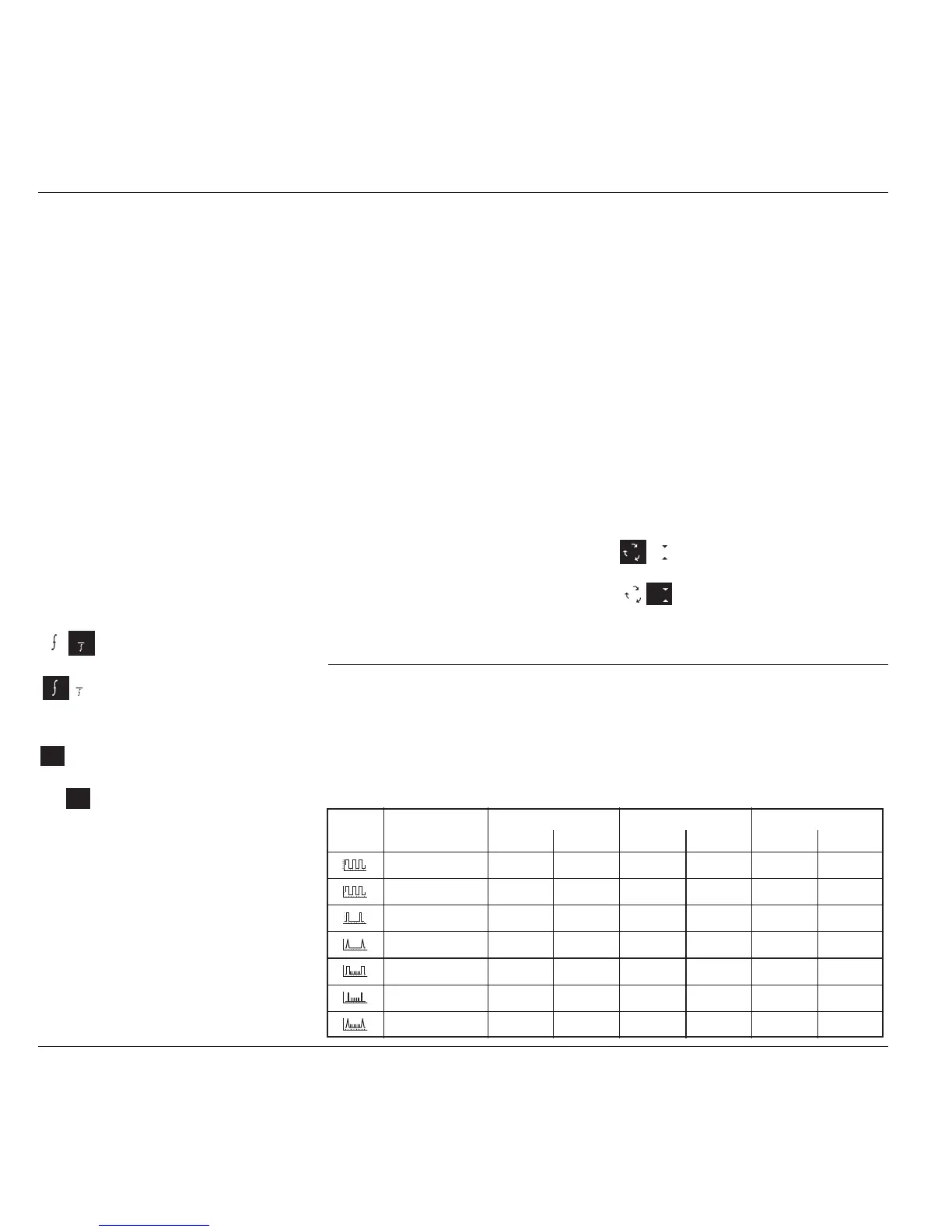
Output Period/Frequency
At maximum and minimum output period, the screen settings of the contributors' values
(Time Marker and Deviation) are limited by both the output period/frequency and the output
voltage. For example:
Marker O/P Time Marker Period Deviation O/P Period
Style Amplitude Min Max Min Max Min Max
100mV - 500mV 450.46ps 50s -45% +45% 450.46ps 55s
1V 626.96ps 50s -45% +45% 909.10ps 55s
100mV - 1V 621.32ns 50s -45% +45% 900.91ns 55s
100mV - 1V 621.32ns 50s -45% +45% 900.91ns 55s
100mV - 1V 13.794ns 50s -45% +45% 20.000ns 55s
100mV - 1V 621.32ns 50s -45% +45% 20.000ns 55s
100mV - 1V 621.32ns 50s -45% +45% 20.000ns 55s