Section 4: Using the Model 9500B — Time Markers Function 4.8-3
Final Width = 215mm
Descriptions assume 9500B/1100
Provided they do not exceed the O/P Period
limits shown, the contributors have the
following adjustments (Scope mode):
a. Time Marker Period (adjustable sequence:
1-2-5 or 1-2-2.5-4-5; default 1.0000µs).
b. Percentage Deviation (a maximum range
of ±45.00% about the value of (
a), at a
resolution of four significant digits, with
two decimal places; default zero). Digit or
direct edit can be used.
c. Output Voltage (directly adjustable only
by preferred sequence between 100mV
and 1V; default 1.0000V).
4.8.4.2 Output Period Editing
The 'Digit' and 'Direct' editing processes follow
the same general rules as for editing voltages
described in paras 4.4.
Tab
Key and Cursors (Scope Mode)
Repeatedly pressing this key moves the cursor
from the default 'Time Marker' (period) to the
Deviation, then to the O/P Amplitude and back
to the 'Time Marker' position. The type of
cursor at each position indicates the type of
adjustment possible.
Time Marker (Scope Mode)
The type of cursor (barred) used for the 'Time
Marker' signifies that the value can be adjusted
only as a step-sequence value using the
key will reduce the 'Time
Marker' period down to 500ps, unless the output
voltage is greater than 500mV.
Square/Sine Waveform Changeover
The changeover from square to sine occurs at
a frequency of 111.101MHz (Period =
9.000819ns), chosen to avoid normal
calibration points.
Frequency Parameter Resolution Conflict
Due to resolution and the step sequence, some
periods cannot be converted exactly into
frequencies. In order to direct attention towards
period at any point at which its reciprocal
cannot be defined exactly, the 'Frequency'
parameter display is given an 'approximately
equal to' symbol (
).
Deviation (Scope and Direct Mode)
Note: In Time Markers function, the
Deviation operates on the Time Marker
interval, to modify the output 'Period' or
'Frequency', and not modify the O/P
Amplitude, as in the other functions.
The triangular type of cursor indicates that all
the cursor keys can be used.
The result of combining the Time Marker
interval and Deviation are shown as the value
of the output 'Period' or 'Frequency'. From the
default 00.00%, the deviation percentage can
be changed to any value within its resolution
between -45% and +45%, providing that the
Time Marker interval does not take the output
'Period' or 'Frequency' value out of its limits.
Output Voltage Amplitude (Scope and
Direct Mode)
The O/P Amplitude is directly adjustable, but
only in the step sequence defined by the
preferences (
Pref
) facility. For this reason the
O/P Amplitude has a 'barred' cursor in both
Scope and Direct modes.
The default 1.0000Vp-p is the maximum output
available. The output voltage can be changed
to any step value between 100mV p-p and 1V
p-p. With Marker Style
, for sinewave
periods less than 909.09ps, the maximum output
voltage available is 500mVp-p.
Output Period/Frequency
From the default 1µs/1MHz, the output period/
frequency can be changed to any value within
its limits as shown in the table for the Marker
Styles.
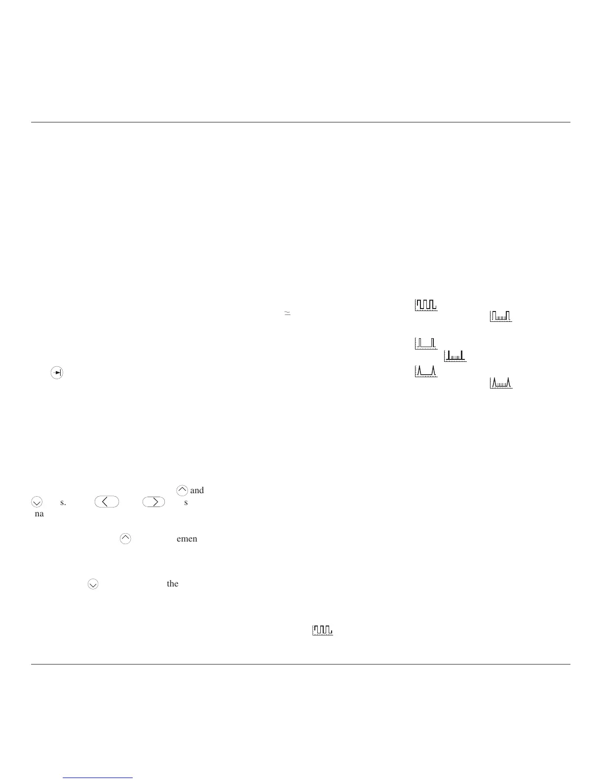
4.8.4.3 Highlighted Marker Styles
Each marker style is available in a version
where each tenth marker is raised to higher
amplitude (highlighted) for Output Periods of
1µs and longer:
a.
Square/Sine: symbol for
highlighted style is
(does not
extend into Sine frequency band).
b.
Pulse: symbol for highlighted
style is
.
c.
Narrow Triangle: symbol for
highlighted style is
.
Limits for these highlighted versions are shown
in the table.