4.6-2 Section 4: Using the Model 9500B — Sine Function
Final Width = 215mm
Descriptions assume 9500B/1100
1
2
5
1.Ø
5
2
1
1.Ø
4.6.3.3 Right Side Screen Keys —
Numeric Entry
Right side screen keys operate on the value in
the edit box, and acting in place of the ↵ key,
exit from Numeric Entry back to Digit Edit/
Sequence Scroll; then set the value as evaluated
in the box:
Cursor on Deviation:
% Evaluates the number in the box in
Deviation Percentage.
V Evaluates the number in the box in
Volts.
mV Evaluates the number in the box in
Millivolts.
Cursor on Frequency:
Hz Evaluates the number in the box in
Hertz.
kHz Evaluates the number in the box in
Kilohertz.
MHz Evaluates the number in the box in
Megahertz.
GHz Evaluates the number in the box in
Gigahertz.
4.6.3.4 Bottom Screen Keys —
Digit Edit/Sequence Scroll
and Numeric Entry
CHANNEL Permits the screen signal setup to
SELECT be routed to any of the five heads,
allowing selection of trigger
channel, trigger ratio and cable
channel (paras 4.5.3).
Currently in Scope mode. Press to
select Direct Mode (paras 4.4.3/4).
Currently in Direct mode. Press to
select Scope Mode (setting the step
sequence to '1, 2, 5' or
'1, 2, 2.5, 4, 5' as chosen using the
Preferences key) (paras 4.4.1/2).
4.6.3 Menu Selections
(Contd.)
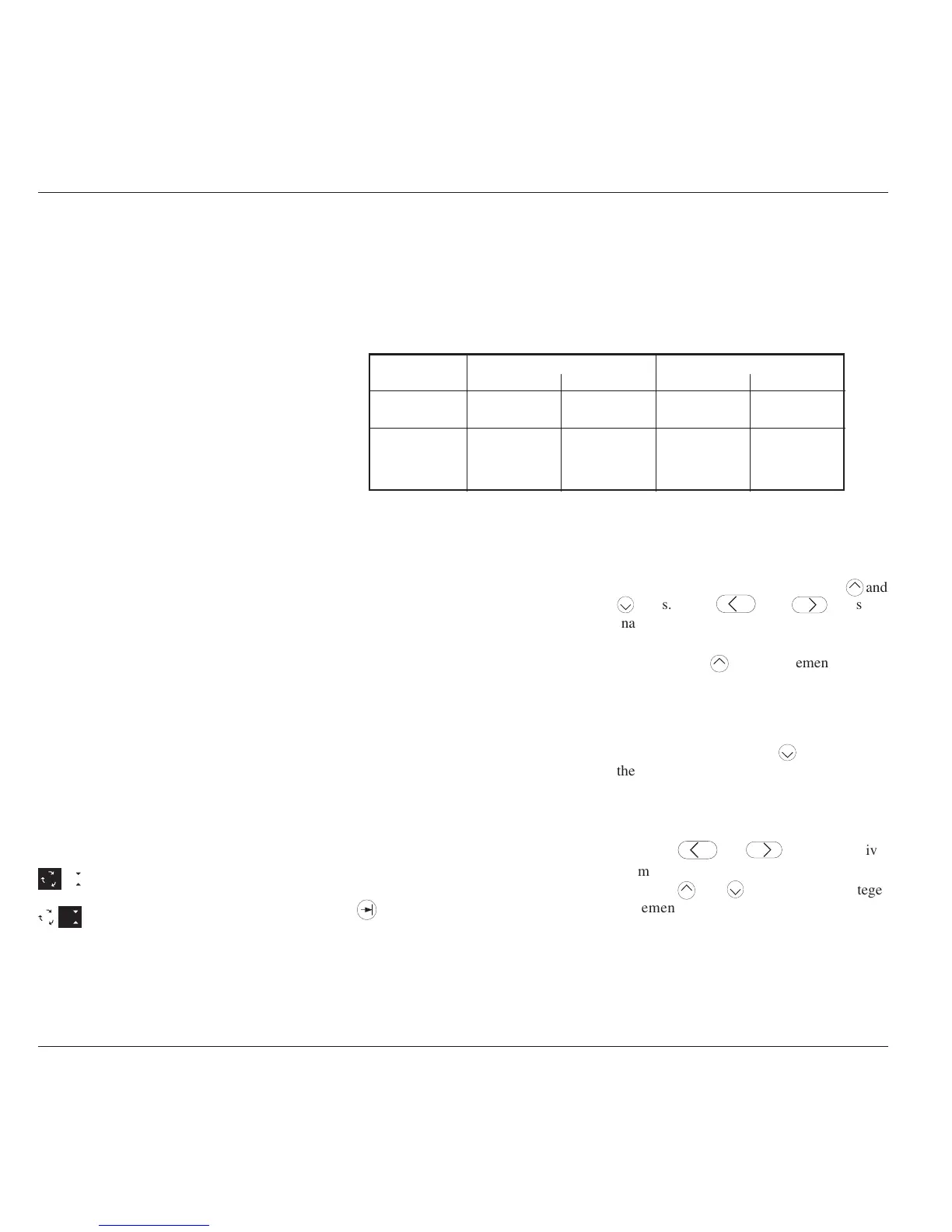
Frequency: 100mHz - 550.00MHz Frequency: 550.01MHz - 1.1GHz
Minimum Maximum Minimum Maximum
Units/Division 1mV/div 2V/div 1mV/div 2V/div
Scaling Multiplier 110110
Deviation -11.20% +11.20% -11.20% +11.20%
Output Voltage 4.44mV p-p 5.56V p-p 4.44mV p-p 3.336V p-p
Limit
Table 4.6.4.1 Sine Function — Output Voltage Limits and Contributors Limits
Amplitude
At maximum and minimum output voltages, the screen settings of the contributors' values
(units/division, scaling multiplier and deviation) are limited by the output voltage itself (refer
to Table 4.6.4.1).
4.6.4 Sine Function Operation
4.6.4.1 Value Editing
Units/Division (Scope Mode)
The type of cursor (barred) used for the units/
division signifies that the value can be adjusted
only as a step-sequence value using the
keys are
inactive.
From the default '5mV/div', the value can be
raised using the
key by increments through
10mV/div, 20mV/div, 50mV/div and so on up
to 2V/div, providing that the other contributors
will not take the output voltage value above
5.56Vp-p (≤550MHz) or 3.336Vp-p
(>550MHz). Similarly, the
key will reduce
the Units/Division down to 1mV/div, unless
the output voltage would fall below 4.44mVp-
p (all frequencies).
Multiplier (Scope Mode)
Again the
keys are inactive.
From the default 'x 6', the value can be changed
using the
keys, by single integer
increments to values between 1 and 10,
providing that the other contributors do not
take the output voltage value out of its limits.
The product of the units/division and multiplier
are shown on the right side of the '=' sign.
Provided they do not exceed the output voltage
limits shown, the contributors have the
following adjustments (Scope mode):
a
. Units/Division in Volts/division in the
adjustable sequence: 1 - 2 - 5 or (using
'Pref') 1 - 2 - 2.5 - 4 - 5; default 5mV/div.
b
. Scaling Multiplier (adjustable through
integers 1 to 10; default 6).
c
. Percentage Deviation (a maximum range
of ±11.20% about the value of (
a
) x (
b
), at
a resolution of four significant digits, with
two decimal places; default zero). Digit
Edit, Sequence Scroll or Numeric Entry
can be used.
d
. Output Voltage (adjustable in Digit Edit/
Sequence Scroll only, by manipulation of
(
a
), (
b
) and (
c
); default 30.000mV).
4.6.4.2 Output Voltage Editing
Editing follows the same general rules as for
editing voltages described in paras 4.4.
Tab
Key and Cursors (Scope Mode)
Repeatedly pressing this key moves the cursor
from the default Units/Division to the
Multiplier, then Deviation, finally to the
Frequency and back to the Units/Division.
The type of cursor at each position indicates
the type of adjustment possible to that value.