Section 9: Verifying the Model 9500B Accuracy Specification 9-33
Final Width = 215mm
9.9.4 Verifying the Load Capacitance Measurement Function ( )
9.9.4.1 Summary
Equipment requirements are given at para 9.9.4.2 and test
interconnections at para 9.9.4.3. Para 9.9.4.4 shows the Verification
Setup.
The Verification Procedure is at para 9.9.4.5.
The Load Capacitance Measurement Function is verified by carrying
out measurements of the capacitance of a calibrated Capacitance
Standard in the sequences given at paras 9.9.4.4 and 9.9.4.5, at the
verification points shown in Table 9.9.4.1.
9.9.4.2 Equipment Requirements
• The UUT Active Head, connected to a verified Model 9500B
Mainframe.
• Two Calibrated Capacitance Units (BNC-terminated):
a. Calibrated value between 15pF and 25pF.
b. Calibrated value between 85pF and 95pF.
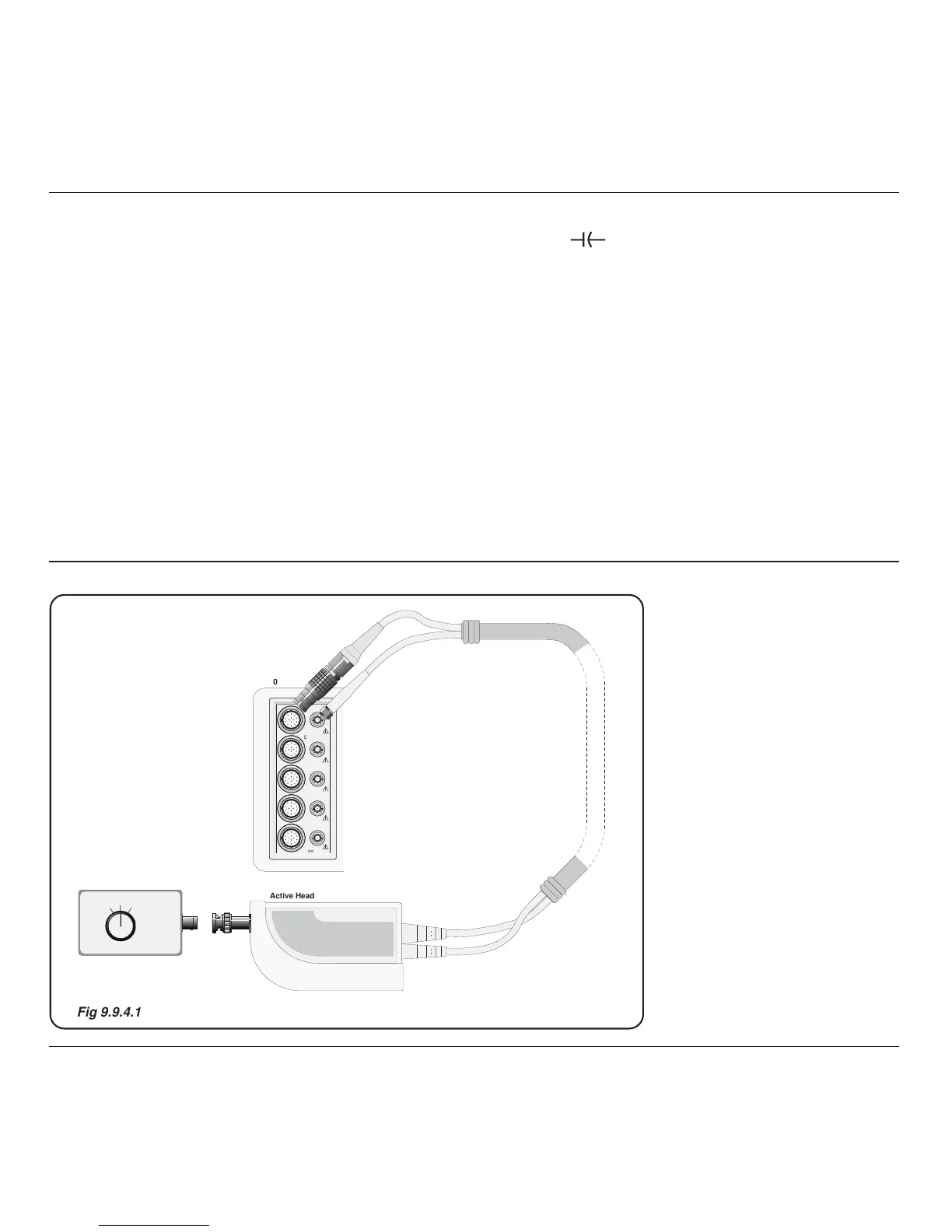
9.9.4.3 Interconnections
Suitable capacitance values can be constructed from a length of coaxial
cable fitted with a BNC connector at one end and open circuit at the
other. Measure the capacitance value with a capacitance bridge. If the
cable is fitted with a female connector, a BNC male/male adapter is
required to interface with the Active Head and must be included in the
capacitance value.
ACTIVE HEAD
INPUT
Off
High CapLow Cap
Calibrated Capacitor Unit