9-34 Section 9: Verifying the Model 9500B Accuracy Specification
Final Width = 215mm
BLANK PAGE (LEFT-HAND)
9.9.4.5 9500B Absolute Tolerance Calculations
1. Refer to Table 9.9.4.1. Ensure that the Test Capacitance Calibrated
Values have been entered for the two Test Capacitors (High and
Low).
2. Use the specification figures to calculate the 9500B Absolute
Tolerance Limits.
Example:
Let us say that the Test Capacitor value has been calibrated at 20pF:
The specification tolerance for this value is: ±2% ± 0.25pF.
±[(2% x 20pF) + 0.25pF] = ±[0.4pF + 0.25pF] = 0.65pF
We must now subtract this value from 20pF for the lower limit
(19.35pF), and add it to 20pF for the higher limit (20.65pF).
3. Enter the 9500B Absolute Tolerance Limits into their respective
columns on Table 9.9.4.1.
9.9.4.4 Verification Setup
1. Copy the Table 9.9.4.1.
2. Test Capacitor Values
a. Ensure that the two Capacitors have been
calibrated.
b. Enter the low and high calibrated values in the
'Capacitance Calibrated Value' column of Table
9.9.4.1.
3. Connections Ensure that the 9500B is connected to the
Capacitance unit (or individual capacitors in turn)
as shown in Fig. 9.9.4.1, and that both instruments
are powered on and warmed up.
4. 9500B a. Ensure that the 9500B is in MANUAL mode.
Select the Aux functions (
Aux key on the right
of the front panel). Press the
soft key on
the bottom row.
b. Select the required output Signal Channel.
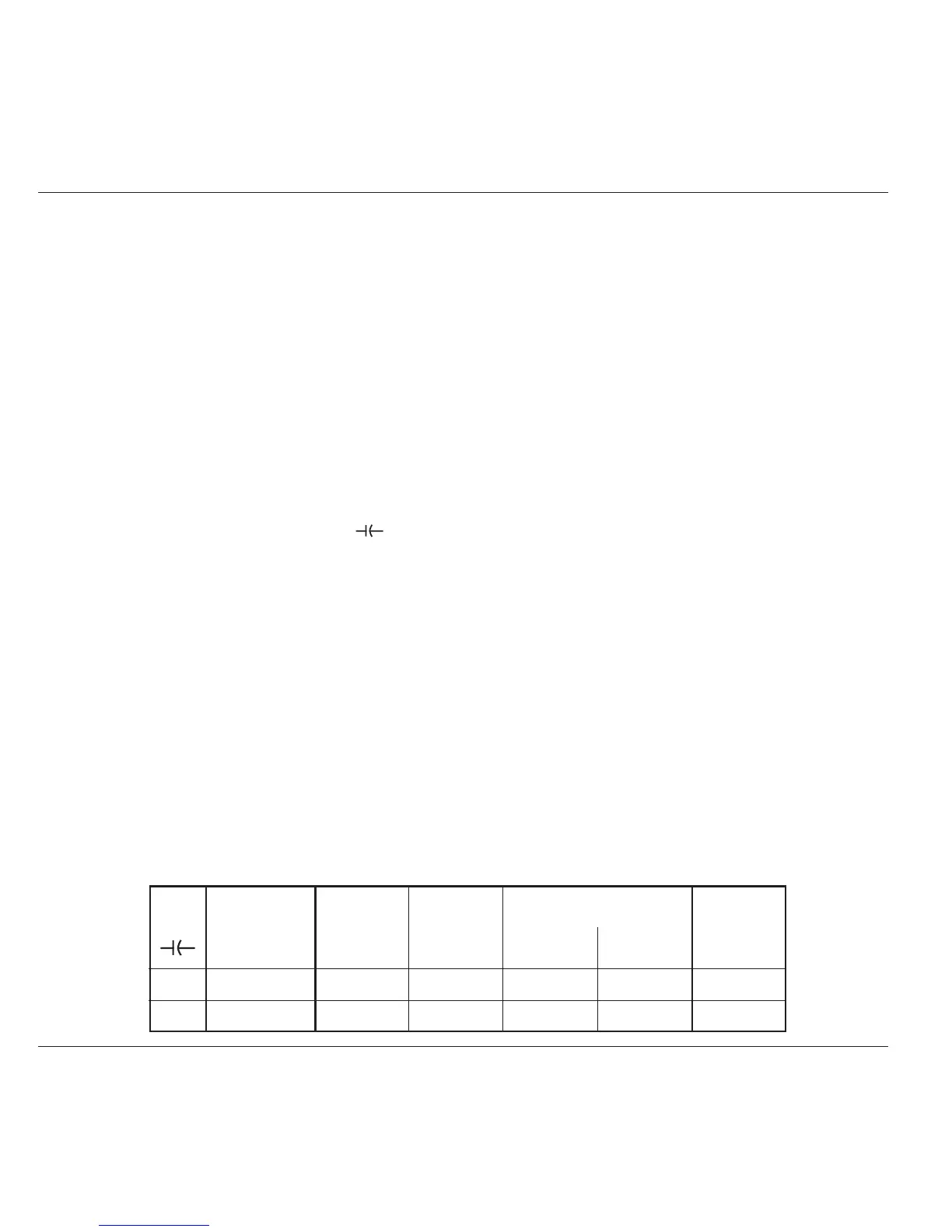
Verif. Capacitance Test 9500B 9500B Absolute Tolerance 9500B
Point. Test Range Capacitance Measurement Limits Measured
Calibrated Spec Lower Higher Value
Value
CAP1 Low: 15-25pF pF ±2% ± 0.25pF pF pF pF
CAP2 High: 85-95pF pF ±3% ± 0.25pF pF pF pF
Table 9.9.4.1 Load Capacitance Measurement Verification
Please copy the following table. Enter the values in the columns on the copy:
9.9.4.6 Verification Procedure
Refer to Table 9.9.4.1. At each verification point shown on the table,
carry out the following operations (1) to (6).
1. Test Cap Select the correct Test Capacitance for the
verification point range.
2. 9500B Set Output ON and wait for the Load Capacitance
reading to settle.
3. Reading b. Record the 9500B reading in the Measured
Value column of the copy of the Table.
c. Check that the Measured Value is at or between
the Absolute Tolerance Limits.
6. 9500B Set Output OFF.