Section 4: Using the Model 9500B — Current Function 4.10-5
Final Width = 215mm
Descriptions assume 9500B/1100
4.10.7.5
UUT Current Probe — Pulse Response
Calibration using the 9500B as an
Adjustable Source
Sequence of Operations
Refer to the table or list of UUT Oscilloscope
amplitude calibration points in the UUT
Oscilloscope Manufacturer's Calibration
Guide.
Follow the sequence of calibration stages as
directed by the guide, and carry out the
following operations (1) to (6) at each stage.
1. 9500B
Use the front panel controls to set the 9500B
Output to the required square wave p-p current
and frequency for the UUT 'Scope amplitude
cal point:
2. UUT 'Scope
a. Select the correct channel for the cal point.
b. Select the correct range for the cal point.
3. 9500B Set Output ON.
4. UUT 'Scope
a. Adjust the sweep speed and trigger level
for a stable display.
b. Observe and note the amplitude response.
5. Calibration
a. Use the 9500B Deviation control to slew
the 9500B Output current until the UUT's
response is appropriate to the 9500B
settings, as detailed in the UUT
Oscilloscope Manufacturer's Calibration
Guide.
b. Record the 9500B screen output current as
detailed in the UUT Oscilloscope
Manufacturer's Calibration Guide.
6. 9500B Set Output OFF.
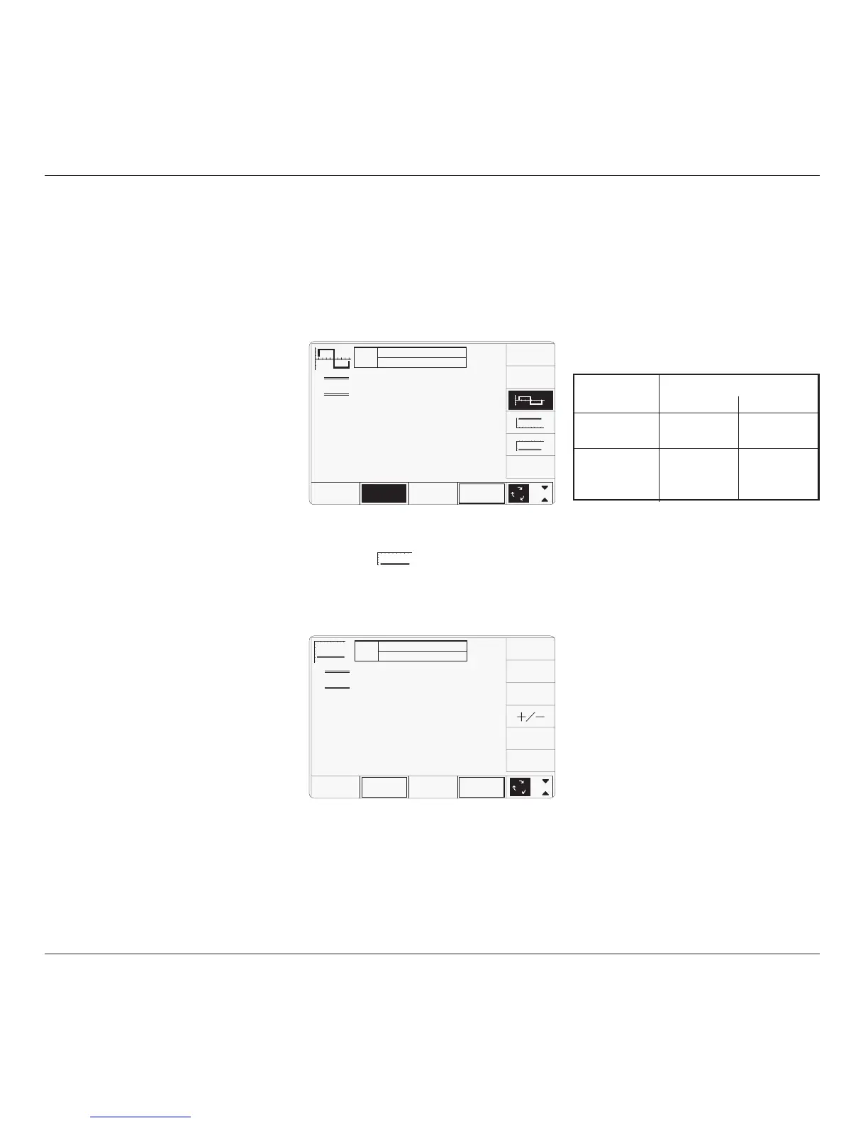
4.10.8.1 Polarity
Waveform Selection Screen
From the power-on default, pressing the
WAVEFORM screen key transfers to the
waveform menu screen:
4.10.8.2 Value Editing
Amplitude
At maximum and minimum output currents,
the screen settings of the contributors' values
(units/division, scaling multiplier and
deviation) are limited by the output current
itself. For example:
4.10.8 DCI Operation
TODAY'S DATE TIME
OFF
SIGNAL CH1 5ØΩ
TRIGGER NONE
x 1Ø
÷ 1Ø
∆ = Ø
1.ØØ mA/div x4 = 4.ØØØØ mA
Deviation
= ØØ.ØØ %
O/P
Amplitude
= -4.ØØØØ mA
WAVE
FORM
CHANNEL
SELECT
1
2
5
1.Ø
Both polarities of DC Current output are listed
merely as different waveforms. As an example,
pressing the
key from the setup shown
above will present the DC function screen,
showing negative values selected (of course,
the frequency parameter has disappeared from
the screen):
Once into DC function, it is not necessary to
change the waveform to change polarity.
Pressing the
+
/
- screen key toggles between
positive and negative DC Current. The polarity
selection is shown by the function icon in the
top left corner, confirmed by the
+ or - sign on
the O/P Amplitude value.
Contributor Limits
Minimum Maximum
Units/Division 20µA/div 50mA/div
Scaling Multiplier 1 10
Deviation -11.20% +11.20%
Output Current ±88.8µA p-p ±111.2mA p-p
Limit
Provided they do not exceed the output current
limits shown, the contributors have the
following adjustments (Scope mode):
a. Units/Division in Volts/division
(adjustable sequence: 1-2-5 or 1-2-2.5-4-
5; default 1mA).
b. Scaling Multiplier (adjustable through
integers 1 to 10; default 4).
c. Percentage Deviation (a maximum range
of ±11.20% about the value of (
a) x (b), at
a resolution of four significant digits, with
two decimal places; default zero). Digit or
direct edit can be used.
d. Output Current (adjustable in digit edit
only, by manipulation of (
a), (b) and (c);
default 4.0000mA).
4.10.8.3 Output Current Editing
The 'Digit' and 'Direct' editing processes follow
the same rules as for editing square waves
(refer to para 4.10.6.2). Obviously no
frequency adjustment is present, and polarity
is changed as described in para 4.10.8.1.
TODAY'S DATE TIME
OFF
SIGNAL CH1 5ØΩ
TRIGGER NONE
1.ØØ mA/div x4 = 4.ØØØØ mA
pk-pk
Deviation
= ØØ.ØØ %
O/P
Amplitude
= 4.ØØØØ mA
pk-pk
Frequency
= 1.ØØØØ kHz
WAVE
FORM
1
2
5
1.Ø
CHANNEL
SELECT