4.5-4 Section 4: Using the Model 9500B — DC/Square Function
Final Width = 215mm
Descriptions assume 9500B/1100
1
2
5
1.Ø
5
2
1
1.Ø
4.5.4.1 Right Side Screen Keys —
Digit Edit / Sequence Scroll
Keys operate on the value marked by the
cursor. The key labels will change depending
on the cursor position, as indicated.:
i. Cursor on Units/div:
X10 Multiplies the Units/div by ten.
÷10 Divides the Units/div by ten.
∆ = Ø Toggles the Deviation value
between the marked value and zero.
Toggles the value between positive
and negative (DC only).
ii. Cursor on Multiplier:
∆ = Ø Toggles the Deviation value
between the marked value and zero.
Toggles the value between positive
and negative (DC only).
iii. Cursor on Deviation:
∆ = Ø Toggles the Deviation value
between the marked value and zero.
Press to set Deviation value in
absolute units.
Press to set Deviation value in
percent of set value.
iv. Cursor on Frequency/Period:
X10 Multiplies the marked value by ten.
÷10 Divides the marked value by ten.
∆ = Ø Toggles the Deviation value
between the marked value and zero.
Press to change display from
Frequency to Period (not DC).
Press to change display from Period
to Frequency (not DC).
4.5.4.2 Right Side Screen
Keys — Numeric Entry
Right side screen keys operate on the
value in the edit box, and acting in place
of the ↵ key, exit from Numeric Entry
back to Digit Edit/Sequence Scroll; then
set the value as evaluated in the box:
Cursor on Deviation:
% Evaluates the number in the
box in Deviation
Percentage.
V Evaluates the number in the
box in Volts.
mV Evaluates the number in the
box in Millivolts.
µV Evaluates the number in the
box in Microvolts.
∆% ∆V
∆% ∆V
1
1
4.5.4 DC/Square Operation
4.5.4.3 Bottom Screen Keys —
Digit Edit, Sequence Scroll
and Numeric Entry
WAVE Provides a second menu screen
FORM for selection between three Square
waveshapes or ±DC.
(paras 4.5.3.7-9).
With output on, the output to the
UUT is grounded, for any waveform
or DC selection.
CHANNEL Permits the screen signal setup to
SELECT be routed to any of the five heads,
allowing selection of trigger
channel, trigger ratio and cable
channel (paras 4.5.3).
Press to select Direct Mode (paras
4.4.3/4).
Press to select Scope Mode (setting
the step sequence to '1, 2, 5' or
'1, 2, 2.5, 4, 5' as chosen using the
Preferences key) (paras 4.4.1/2).
4.5.5 Square Operation
4.5.5.1 Value Editing
Amplitude
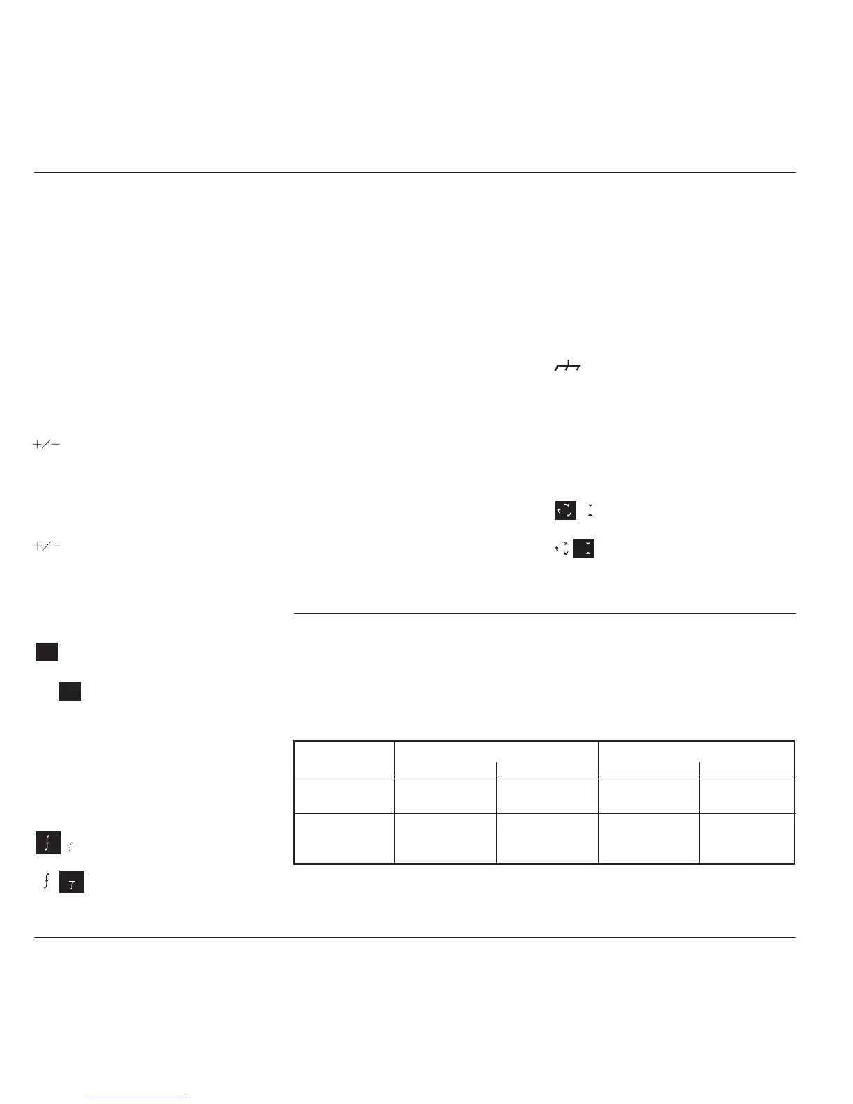
At maximum and minimum output voltages, the screen settings of the contributors' values
(units/division, scaling multiplier and deviation) are limited by the output voltage itself. For
example:
Contributor
Ω
LOAD
= 1M
Ω
Ω
LOAD
= 50
Ω
Minimum Maximum Minimum Maximum
Units/Division 10µV/div 50V/div 10µV/div 2V/div
Scaling Multiplier 1 10 1 10
Deviation -11.20% +11.20% -11.20% +11.20%
Output Voltage 35.52µV p-p 222.4V p-p 35.52µV p-p 5.56V p-p
Limit
Provided they do not exceed the output voltage limits shown, the contributors have the following
adjustments (Scope mode):