Section 4: Using the Model 9500B — DC/Square Function 4.5-5
Final Width = 215mm
Descriptions assume 9500B/1100
a. Units/Division in Volts/division
(adjustable sequence: 1-2-5 or 1-2-2.5-4-
5; default 5mV).
b. Scaling Multiplier (adjustable through
integers 1 to 10; default 4).
c. Percentage Deviation (a maximum range
of ±11.20% about the value of (
a) x (b), at
a resolution of four significant digits, with
two decimal places; default zero). Digit
Edit or Numeric Entry can be used.
d. Output Voltage (adjustable only by
manipulation of (
a), (b) and (c); default
20.000mV).
4.5.5.2 Output Voltage Editing
The editing processes follow the same general
rules as for editing voltages described in paras
4.4.
Tab
Key and Cursors (Scope Mode)
Repeatedly pressing this key moves the cursor
from the default units/division to the Multiplier,
then to the Deviation and back to the units/
division. The type of cursor at each position
indicates the type of adjustment possible.
Units/Division (Scope Mode)
The type of cursor (barred) used for the units/
division signifies that the value can be adjusted
only as a step-sequence value using the
keys, by single integer
increments to values between 1 and 10,
providing that the other contributors do not
take the output voltage value out of its limits.
The product of the units/division and multiplier
are shown on the right side of the '=' sign.
Deviation (Scope and Direct Mode)
The triangular type of cursor indicates that all
the cursor keys can be used.
From the default 00.00%, the deviation
percentage can be changed to any value within
its resolution between -11.20% and +11.20%,
providing that the other contributors do not
take the output voltage value out of its limits.
The result of combining the units/division,
multiplier and deviation are shown as the value
of 'O/P Volts p-p'.
Output Voltage (Scope and Direct Mode)
The O/P Amplitude is only adjustable by means
of its contributors.
From the default 20.000mV p-p, the output
voltage can be changed to any value within its
resolution between 35.52µV p-p (both 50Ω
and 1MΩ loads) and 5.56V p-p (50Ω load) or
222.40V p-p (1MΩ load).
Frequency (Scope and Direct Mode)
From the default 1kHz, the output frequency
can be changed to any value within its resolution
between 10Hz and 100kHz.
4.5.5.3 Low Voltage (LV) and
High Voltage (HV) States
In the interests of safety, to avoid electric
shock, the 9500B incorporates a high-voltage
interlock system for DC/Square and High Edge
functions. The interlock threshold voltage can
be chosen by the user between 10V and 110V,
otherwise a default threshold value of 100V is
set. The active threshold value is stored in non-
volatile memory.
Any voltage below the threshold can be output
without hindrance, but voltages on or above
the threshold cannot be output without
deliberate action being taken to enter the high
voltage (HV) state. Once entered, a continuous
audible signal acts as a reminder that HV state
is active.
The system exits from HV state when the
output voltage is brought down below HV
state's lower limit. This is always 10% less
than the active threshold value, allowing some
adjustment of output without the irritation of
having to change states.
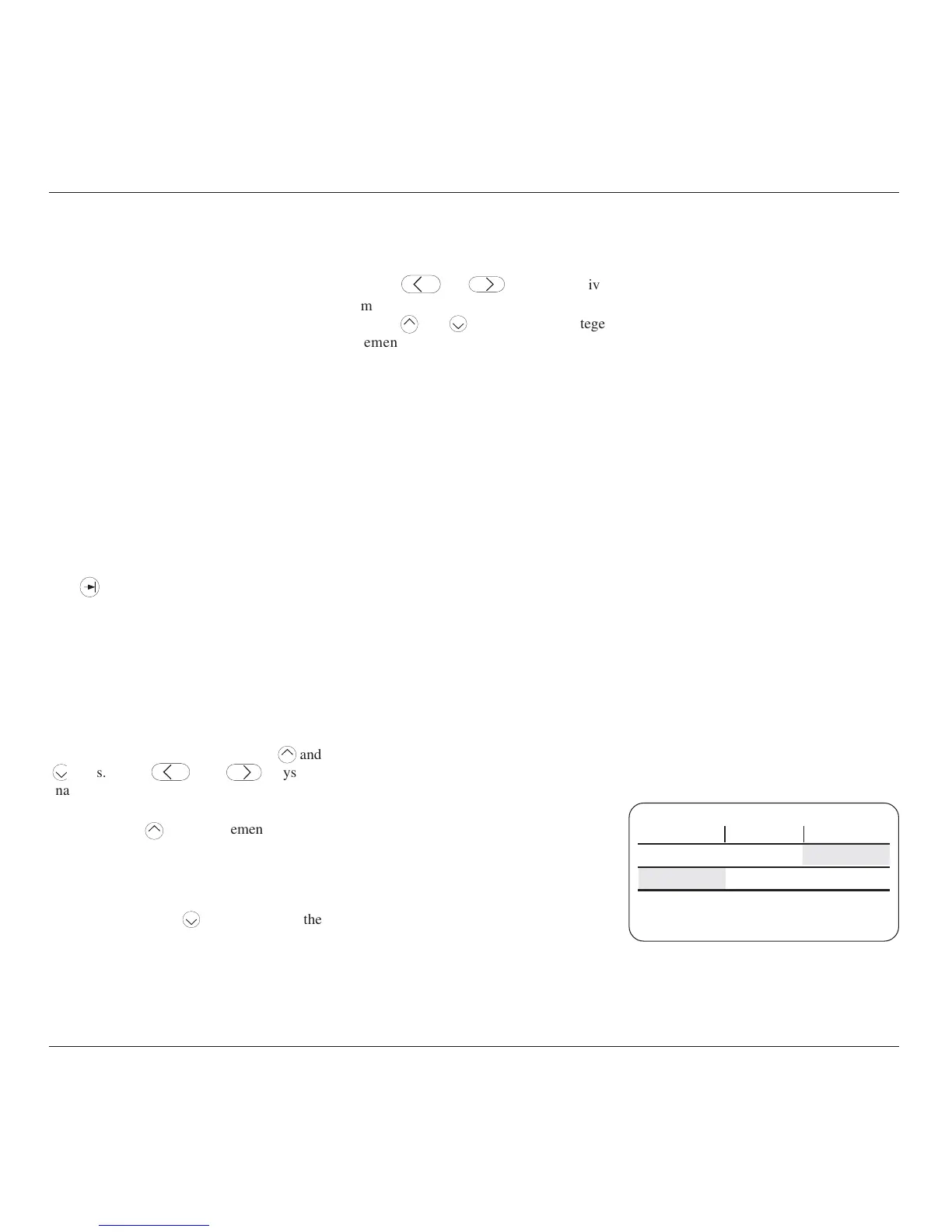
Each threshold value is related to the output
value set on the screen, including Deviation.
The default state boundaries are shown in Fig.
4.5.1. The values given in the figure translate
to DC volts in DCV function, and pk-pk volts
in Square and High Edge functions.
Low Voltage State
→
←
High Voltage State
100V90V
Fig. 4.5.1 Default Settings of
Low and High Voltage States
continued overleaf
→