Section 4: Using the Model 9500B — Linear Ramp Function 4.12-1
Final Width = 215mm
Descriptions assume 9500B/1100
The 9500B has auto-selected a Ramp Time of
1.0000s. Trigger is auto-selected: 'TRIG
START', not 'TRIG MID'. O/P Amplitude is
fixed at 1.0000V.
4.12.3 Menu Selections
Signal Channel selection, Trigger Channel
selection, Cable selection and Trigger Ratio all
operate in the same way as in DC/Square
function. Refer to paras 4.5.3.
Note: Without Option 5, only one signal
channel and one trigger channel is
available.
4.12.3.1 Retained Channel Memory
Refer to para 4.5.3.6.
4.12.3.2 Scope Mode Only
The function operates only in Scope mode.
Ramp Time is the only signal variable,
operating on a step sequence as selected in
'
Pref'. Refer to Section 3, sub-section 3.3.
4.12 Linear Ramp Function
This sub-section is a guide to the use of the
9500B for generating Linear Ramps for error
code detection and trigger level marker
calibrations.
For those users who require more detailed
instructions for interconnections, and
manipulating the front panel controls, refer to
sub-sections 4.2, 4.3 and 4.4. Section 4.12 is
divided into the following sub-sections:
4.12.1 Introduction .................................................. 4.12-1
4.12.2 Default Settings ............................................ 4.12-1
4.12.3 Menu Selections ........................................... 4.12-1
4.12.3.1 Retained Channel Memory ........... 4.12-1
4.12.3.2 Scope Mode Only ........................ 4.12-1
4.12.3.3 Right Side Screen Keys ................ 4.12-1
4.12.3.4 Bottom Screen Keys ..................... 4.12-1
4.12.4 Linear Ramp Operation ................................. 4.12-1
4.12.4.1 Value Editing ................................ 4.12-1
4.12.5 Using the 9500B Linear Ramp Function for
Error Code Detection and
Trigger Level Marker Checks ........................ 4.12-2
4.12.5.1 Introduction .................................. 4.12-2
4.12.5.2 Interconnections ........................... 4.12-2
4.12.5.3 9500B and UUT Oscilloscope
Setup ............................................ 4.12-2
4.12.5.4 Error Code Detection —
Sequence of Operations ............... 4.12-2
4.12.5.5 Trigger Level —
Sequence of Operations ............... 4.12-2
4.12.3.3 Right Side Screen Keys
x 1Ø
Increases Ramp Time by a factor of
10 within max. and min. limits.
÷ 1Ø
Decreases Ramp Time by a factor
of 10 within max. and min. limits.
UUT Scope trigger currently at start
code. Press to provide trigger at
center code.
UUT Scope trigger currently at
center code. Press to provide trigger
at start code.
4.12.3.4 Bottom Screen Keys
CHANNEL Permits the screen signal setup to
SELECT be routed to any of the five heads,
allowing selection of trigger
channel, trigger ratio, cable channel
and expected load (paras 4.5.3).
4.12.4 Linear Ramp Operation
4.12.4.1 Value Editing
Amplitude
Amplitude is fixed at 1.0000V pk-pk and cannot
be edited.
Bias
The waveform is symmetrical about ground.
Ramp Time
From the default 1s, the ramp time can be
changed in decades from 1ms to 1s.
Waveform Period
The ramp times are part of waveforms with the
following periods:
TRIG
START
TRIG
MID
TRIG
START
TRIG
MID
Ramp Time Waveform Period
1s 3s
100ms 300ms
10ms 30ms
1ms 3ms
4.12.2 Default Settings
When Manual mode is selected the system
defaults into DC/Square function and shows
the DC/Square function initial menu screen.
The Linear Ramp function is accessed by first
pressing the 'Aux' key on the right of the
'OSCILLOSCOPE CALIBRATOR' panel,
then pressing the soft key on the right
of the screen.
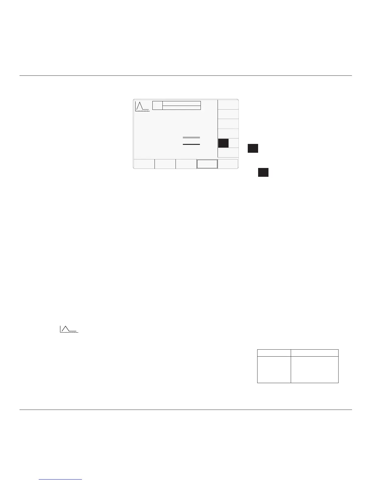
Whenever the Linear Ramp menu screen is
opened, except on recovery from a standby
period, it will appear with the following default
settings:
TODAY'S DATE TIME
OFF
SIGNAL CH1 5ØΩ
TRIGGER NONE
O/P
Amplitude
= 1.ØØØØ V
pk-pk
Ramp Time
= 1.ØØØØ s
CHANNEL
SELECT
TRIG
START
TRIG
MID
x 1Ø
÷ 1Ø
4.12.1 Introduction