Section 2: Installing the Model 9500B 2-9
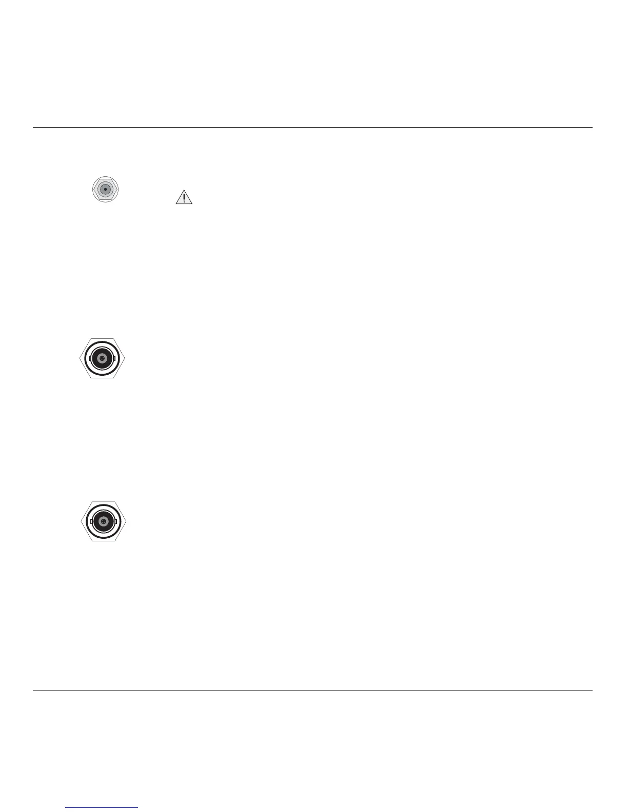
AUXILIARY
INPUT
≤ 40Vpk
REF FREQUENCY
INPUT
≤ 5Vpk
50Ω
REF FREQUENCY
OUTPUT
1V pk-pk nom
into 50Ω
2.9 Care of Microwave Connectors
It is necessary to observe certain basic precautions when using microwave
connectors, in order to achieve accurate and repeatable calibration and
measurement results. This will also help to extend connector life.
Good practice includes:
• When not in use, ensure that connectors are kept clean. This is best
done by using a plastic endcap. Avoid touching components whose
function is to make electrical contact.
• Visually inspect all connectors, looking for dents, scratches and
metal particles. Never use damaged connectors.
• Clean connectors properly, particularly connector threads and
dielectric faces. Try compressed air first, and if this is insufficient,
use isopropyl alcohol. Avoid spillage, and never use abrasives.
• When making connections, be careful to align connectors carefully,
avoiding bending forces. Always make the initial connection
lightly to avoid cross-threading, and use a correctly-set torque
wrench for final tightening.
2.8.4 Auxiliary Input (Rear Panel)
This SMC connector is located at the upper center of the rear panel,
providing an internal, passive, relay switched route for a user's external
calibration signal, via any one of five output channels to an Active
Head's BNC or PC3.5 connector .
Internal controls are provided (via front-panel keys or via the IEEE-488
/ SCPI interface) to switch the signal between channels. For further
details see Section 4, para 4.15.5 and Section 6, para 6.6.5.17.
2.8.5 Ref Frequency Input (Rear Panel)
This BNC connector is located at the middle center of the rear panel,
providing an input for a signal of good frequency accuracy, for use as
a frequency reference in the 9500B.
Internal controls are provided (via front-panel keys in Configuration
mode) to select the signal as reference. For further details see Section
3, para 3.4.3.10.
2.8.6 Ref Frequency Output (Rear Panel)
This BNC connector is located at the lower center of the rear panel,
providing an output reference signal of the same frequency accuracy as
the 9500B.
Internal controls are provided (via front-panel keys in Configuration
mode) to select the signal as reference. For further details see Section
3, para 3.4.3.11.