Section 9: Verifying the Model 9500B Accuracy Specification 9-13
Final Width = 215mm
9.8.4.1 Summary
Equipment requirements are given at para 9.8.4.2 and test
interconnections at para 9.8.4.3.
The Time Markers Function is verified by carrying out measurements
of Period in the sequence given at paras 9.8.4.5, at the verification
points shown in Table 9.8.4.1.
9.8.4.2 Equipment Requirements
• The UUT Model 9500B Mainframe, with 9510 or 9530 Active
Head.
• Digital counter for 0.25ppm clock accuracy measurements.
Example: Hewlett Packard Model HP53131A with Option 012.
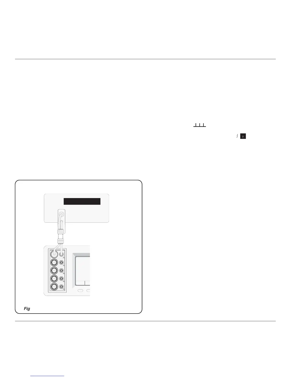
9.8.4.3 Interconnections
Refer to Fig 9.8.4.1.
9.8.4.4 Verification Setup
1. Connections Connect the 9500B to the Counter as shown in Para
9.8.4.1, and ensure that both instruments are
powered ON and warmed up.
2. Counter Select the required function to measure period.
3. 9500B a. Ensure that the 9500B is in MANUAL mode
and then select the Time Markers function
(
key).
b. Use the bottom soft key on the right of the
screen, highlighting 1/f (
1
), to view output
Period on the screen.
c. Select the required output Signal Channel (50Ω
or 1MΩ Load as required), trigger channel and
Trigger Ratio (if required).
230V PK MAX
CH 1
CH 2
CH 3
CH 4
CH 5
Frequency Counter
9500