9-12 Section 9: Verifying the Model 9500B Accuracy Specification
Final Width = 215mm
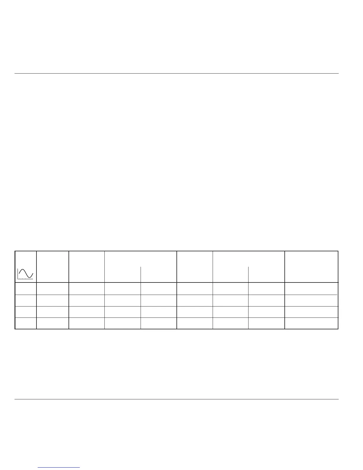
Verif. Frequency Output Absolute Tolerance Output Absolute Tolerance Measured
Point. Voltage Limits (pk-pk) Voltage Limits (RMS) Value
(pk-pk) Lower Higher (RMS) Lower Higher (RMS)
SIN1 1kHz 4.8000V 4.632V 4.968V 1.69706V 1.6377V 1.7565V
SIN2 45kHz 4.8000V 4.632V 4.968V 1.69706V 1.6377V 1.7565V
SIN3 1kHz 1.9000V 1.8335V 1.9665V 0.67175V 0.6482V 0.6953V
SIN4 45kHz 1.9000V 1.8335V 1.9665V 0.67175V 0.6482V 0.6953V
Table 9.8.3.1 Sine Verification into 50
Ω
Load
Please copy the following table.
Enter the measurements in the Measured Value column on the copy:
9.8.3.5 Verification Procedure
Copy the table: 9.8.3.1. Follow the correct sequence of verification points as shown on the table, and carry out the following operations (1) to
(7) at each verification point.
N.B. For Operation (6), the RMS Output Voltage values, and RMS
Absolute Tolerance Limits have been derived using the following
factor for the output waveform:
(at 1kHz: RMS = 0.5 x 0.707106781 x pk-pk)
Note: This factor applies only when the Standards DMM
input is AC-Coupled through a large capacitance.
It is based on the use of a model 4955 set to 'SQV 50 Ω'.
6. Amplitude a. Measure the RMS Output Voltage value.
b. Record this value in the Measured Value
column of the copy of the Table.
c. Check that the Measured Value is at or between
the Absolute Tolerance Limits.
7. 9500B Set Output OFF.
1. Verification Points Refer to Table 9.8.3.1.
2. DMM Select the correct RMS Voltage range for the
verification point RMS Output Voltage.
3. 9500B Set the Output Volts p-p as required for the
verification point:
4. 4955 If using the Model 4955 Calibration Adaptor, set its
switch to 'SQV 50 Ω'. If not using the Model 4955,
ensure that the DMM input is AC-coupled at 50Ω
input impedance.
5. 9500B Set Output ON and wait for the DMM reading to
settle.