Section 4: Using the Model 9500B — Overload Pulse Function 4.13-1
Final Width = 215mm
Descriptions assume 9500B/1100
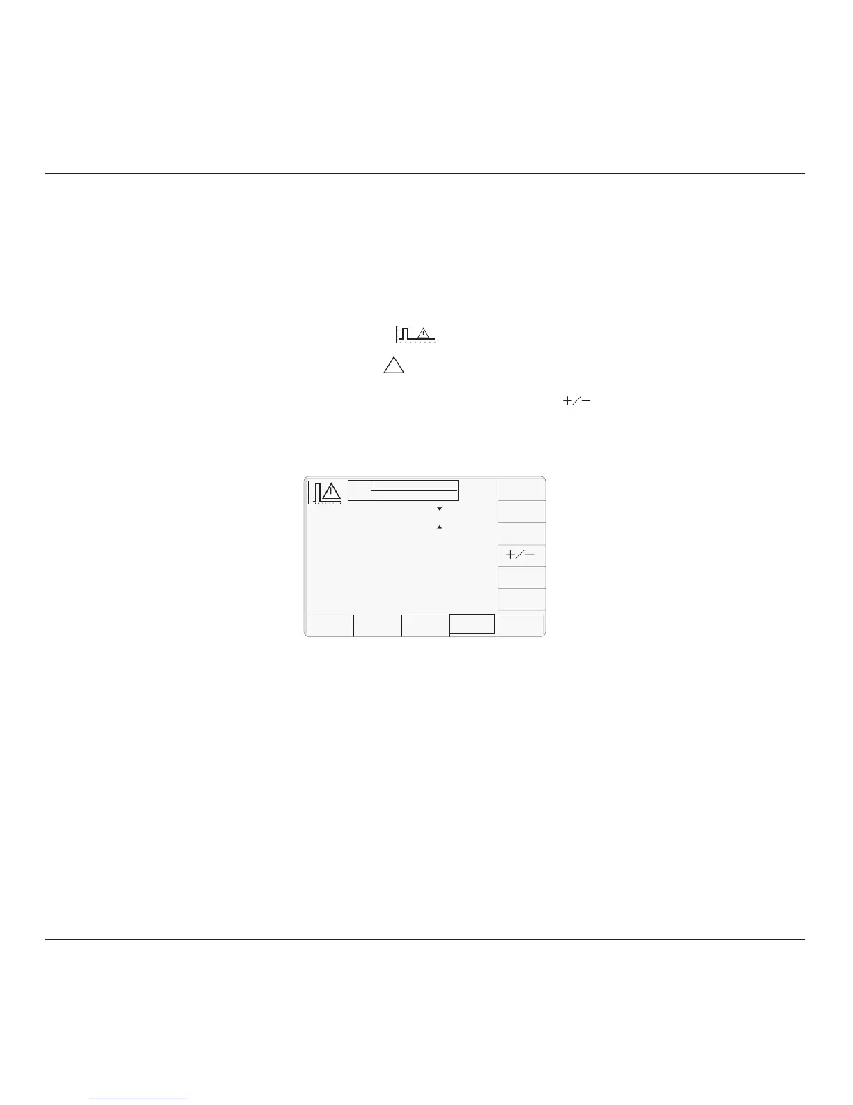
The above default screen has auto-selected the
positive pulse waveform, as indicated by the
icon in the top left corner. Amplitude is
variable between 5 Volts and 20 Volts (default).
Pulse Energy is variable between 1.6 Joules
(default) and 50 Joules. Power into 50Ω and
Pulse Duration are calculated from the voltage
and energy settings.
4.13.4 Menu Selections
Signal Channel selection, Trigger Channel
selection, Cable selection and Trigger Ratio all
operate in the same way as in DC/Square
function. Refer to paras 4.5.3.
Note: Without Option 5, only one signal
channel and one trigger channel is
available.
4.13.3 Default Settings
When Manual mode is selected the system
defaults into DC/Square function and shows
the DC/Square function initial menu screen.
The Overload Pulse function is accessed by
first pressing the 'Aux' key on the right of the
'OSCILLOSCOPE CALIBRATOR' panel,
then pressing the
soft key on the right
of the screen.
Caution: The
!
symbol indicates that care
must be taken when applying the overload
pulse to UUT oscilloscope inputs.
Whenever the Overload Pulse menu screen is
opened, except on recovery from a standby
period, it will appear with the following default
settings:
4.13 Overload Pulse Function
This sub-section is a guide to the use of the
9500B for generating Overload Pulses for use
in testing oscilloscope 50Ω terminator
Protection.
For those users who require more detailed
instructions for interconnections, and
manipulating the front panel controls, refer to
sub-sections 4.2, 4.3 and 4.4. Section 4.13 is
divided into the following sub-sections:
4.13.1 Introduction .................................................. 4.13-1
4.13.2 Overload Protection Test .............................. 4.13-1
4.13.3 Default Settings ............................................ 4.13-1
4.13.4 Menu Selections ........................................... 4.13-1
4.13.4.1 Retained Channel Memory ........... 4.13-1
4.13.5 Overload Pulse Operation ............................. 4.13-1
4.13.5.1 Right Side Screen Keys -
Digit Edit ...................................... 4.13-1
4.13.5.2 Right Side Screen Keys -
Direct Edit .................................... 4.13-1
4.13.5.3 Bottom Screen Keys -
Digit and Direct Edit ..................... 4.13-1
4.13.5.4 Value Editing ................................ 4.13-2
4.13.5.5 Overload Pulse Editing ................. 4.13-2
4.13.6 Using the 9500B to Test the Overload Response
of a UUT Oscilloscope .................................. 4.13-2
4.13.6.1 Introduction .................................. 4.13-2
4.13.6.2 Interconnections ........................... 4.13-2
4.13.6.3 9500B and UUT Scope Setup ....... 4.13-2
4.13.6.4 Sequence of Operations ............... 4.13-2
4.13.2 Overload Protection Test
Some oscilloscope manufacturers protect the
internal 50Ω terminator with a voltage or
thermal detector.
Verification of the protection function requires
limited-duration application of overload, during
which the protection should react and open-
circuit the 50Ω terminator.
With the 9500B 'Auxiliary' Overload Pulse
function selected, the Overload Pulse can be
set to the UUT oscilloscope's overload test
requirements, using 9500B front panel controls.
The pulse is triggered as a single event, and
cannot be repeated at intervals less than 3
seconds. Sync or 100Hz triggers are provided
if required.
4.13.1 Introduction
4.13.4.1 Retained Channel Memory
Refer to para 4.5.3.6.
4.13.5
Overload Pulse Operation
4.13.5.1 Right Side Screen Keys —
Digit Edit
Keys operate on the value marked by the
cursor. The key labels do not change, regardless
of the cursor position.:
Toggles the value between positive
and negative pulses.
TRIG Press to trigger a single shot of
PULSE the specified pulse output.
No further pulse can be triggered
within three seconds, otherwise a
screen message will appear.
4.13.5.2 Right Side Screen Keys —
Direct Edit
Right side screen keys operate on the value in
the edit box, and acting in place of the ↵ key,
exit from Direct Edit back to Digit Edit; then
set the value as evaluated in the box:
a. Cursor on Amplitude:
V Evaluates the number in the box in
Volts.
b. Cursor on Pulse Energy:
J Evaluates the number in the box in
Joules.
4.13.5.3 Bottom Screen Keys —
Digit and Direct Edit
CHANNEL Permits the screen signal setup to
SELECT be routed to any of the five heads,
allowing selection of trigger
channel, trigger ratio and cable
channel (paras 4.5.3).
AUTO Produces a train of triggers at 100Hz
TRIG to trigger the UUT oscilloscope
continuously.
continued overleaf
→
TODAY'S DATE TIME
OFF
SIGNAL CH1 5ØΩ
TRIGGER NONE
Amplitude
= 2Ø.Ø V
Pulse Energy
= Ø1.6 J
Power In 50Ω = 8.ØØØØ W
Duration
= 2ØØ.ØØ ms
CHANNEL
SELECT
TRIG
PULSE
AUTO
TRIG